


20
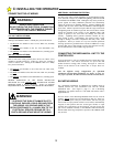
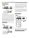
TIMER TO CLOSE SETTING
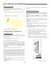
The Timer to Close is controlled by the switch in position #3.
If Switch #3 is set OFF, the Timer to Close function will operate after
the gate has opened.
If Switch #3 is set ON, the Timer to Close function will be disabled.
APPLYING POWER TO THE HDSWG 1000
PRE-POWER CHECK LIST
Before applying power to the HDSWG 1000 for the first time, go
through the following check list to ensure that all is in order for the
application of power.
1. Check that the HDSWG 1000 power switch is off.
2. Check that the breaker at the power panel is on.
3. With a voltmeter on the proper scale, check that the line voltage at
the input to the HDSWG 1000 is the voltage that is expected.
Connection of a 115 VAC HDSWG 1000 to an unexpected 230 VAC
line is a common occurence. This will cause readily identifiable
board failure that WILL NOT BE COVERED UNDER
WARRANTY.
4. Manually move the gate to the center of the gate opening.
5. Make sure the Torque Limiter is properly adjusted to slip under a
load when a moderate amount of force is applied to the gate in the
center of its travel. If the adjustment is too loose, the overload
sensitivity will not funtion properly and the Torque Limiter may slip
when the gate is under a wind loading. Start by tightening the large
nut on the Torque Limiter to 35 ft-lbs/in. To fine tune, increase or
decrease this by approximately 5 ft-lbs/in. increments. When a
satisfactory setting is found, tighten the set screw in the side of the
large nut.
6. Make sure that the proper selection has been made at the
Switch selectable options.
7. Make sure that the overload sensitivity is set to its preliminary start
up position.
8. Remove the 15 AMP fuse at the Backplane of the HDSWG 1000.
(Motor fuse.)
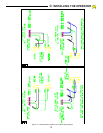
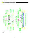
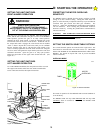
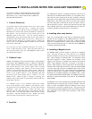
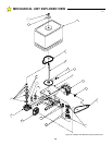
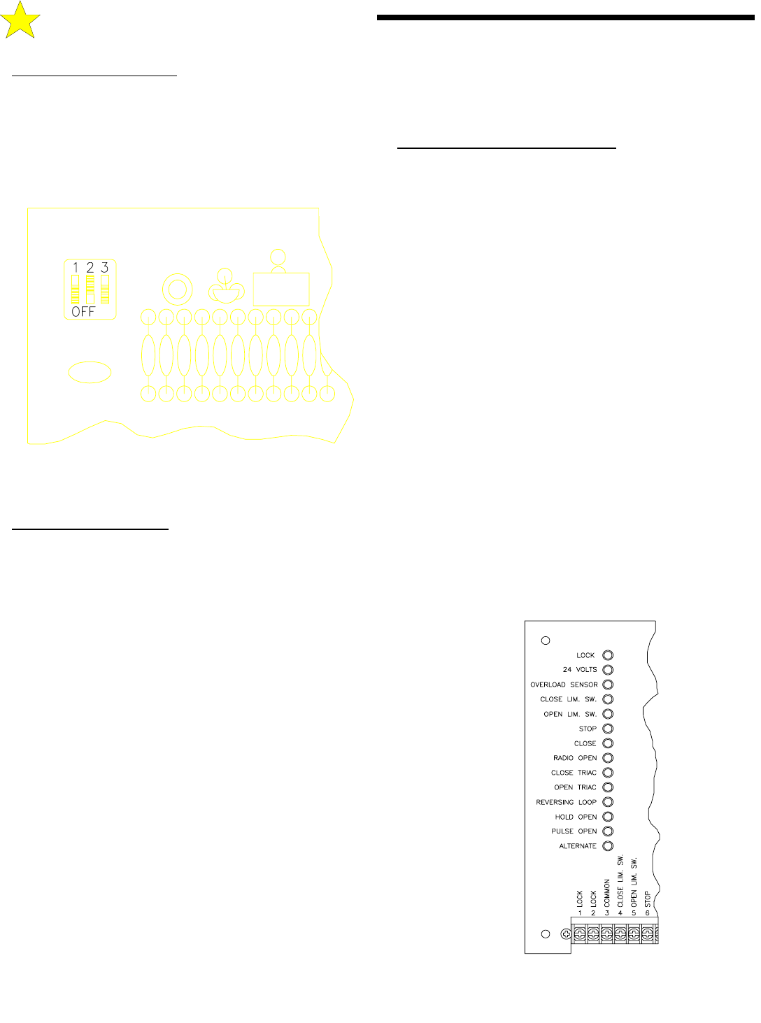
CHECKING THE INDICATOR LIGHTS
There are 14 indicator lights on the Backplane of the HDSWG 1000.
See Figure 21. These lights are used to verify proper operation of the
HDSWG 1000.
TURN ON THE MAIN POWER SWITCH TO THE HDSWG
1000.
•
Note that the 24 V lamp is lighted. This indicates that power is
applied to the Backplane and boards and the power supply is
functioning
•
Note that no other lamps are lighted.
•
Connect one end of a short piece of wire (not supplied) to terminal
#13 (COMMON).
•
With the other end of this wire, (make sure that this loose end is
free of insulation), touch the following terminals and observe the
noted response of the lamps.
1. Terminal #3, Close Lim Sw.: Close Lim Sw light is ON.
2. Terminal #4, Open Lim Sw,: Open Lim Sw light is ON.
3. Terminal #8, Radio Open.: Radio Open light is ON, Open
Triac light is ON and Lock light is ON.
4. Remove wire from Terminal #8, Radio Open. Radio Open
light goes OUT, Open Triac light stays ON, Lock light stays
ON.
5. Terminal #7, Close,: Both Open and Close Triac lights are
momentarily ON, then Open Triac Light goes OUT and Close
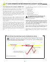
NOTE: SWITCHES 1 AND 2 ARE NOT USED
104897
Figure 20: TIMER TO CLOSE SETTINGS
D:
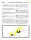
STARTING THE OPERATOR
104898
Figure 21: Indicator Lights