


VIKING TECHNICAL SUPPORT 1.800.908.0884
3
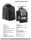
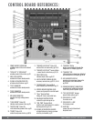
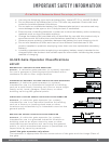
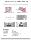
OPERATOR REFERENCES:
1.
COVER BOLTS
2.
OUTPUT SHAFT COVER (HAT)
3.
MAIN COVER ASSEMBLY
4.
MANUAL RELEASE HANDLE
releases the clutch to allow for manual operation
5.
CLUTCH KEY
install if application does not require clutch to slip;
remove to manually operate the gate
6.
OUTPUT ARM
connects the Arm Assembly to Clutch & Handle
Assembly
7.
VFLEX CONTROL BOARD
8.
MOTOR SWITCH
discontinues power to the motor; also serves as
a breaker that will self-trip to protect the motor
circuitry
9.
BATTERY SWITCH
disconnects batteries from the charging circuit
during troubleshooting
10.
MAIN AC POWER SWITCH
discontinues the 115/230VAC power supplied to the
operator
11.
EMI FUSE
main power supply protection
12.
MODULAR POWER BOX ASSEMBLY
removable; provides a convenient solution for
optional low voltage installations
13.
LOOP RACK
for convenient loop detector installation
14.
J-BOX
high voltage power supply connection
15.
COVER BOLT MOUNTING BRACKET