


VIKING TECHNICAL SUPPORT 1.800.908.0884
18
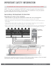
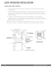
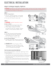
High Voltage Supply Option
!
Caution: Always turn off power breakers when working with high voltage. DO NOT
connect the “Power Harness” to the Control Board until the electrical installation is
complete and ready for verification.
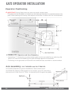
ELECTRICAL INSTALLATION
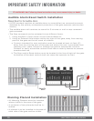
Ground Rod
Earth Ground
2a
1a
1b
3b
3c
3d
Tips for proper ground installation:
To minimize the effects caused by lightning, follow
these guidelines.
•
Use a ground rod to provide a ground reference.
•
Consult your city code and be aware of under-ground
services in the site of the gate operator to prevent
inconveniences.
•
Always use a single bonding point for grounding.
•
All ground wires must be as short and as thick as
possible.
•
Prevent unnecessary turns or loops in all ground
wires.
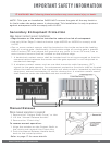
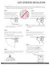
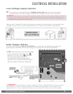
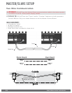
STEP 2
!
WARNING: SINGLE PHASE AC ONLY
At the “J-Box”:
a.
Connect the incoming power wires,
matching the wire color codes.
b.
If the supply voltage is 120VAC,
connect the red wire, labeled “Outlet
Power”, to the neutral (white) wires.
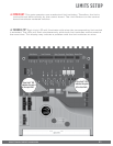
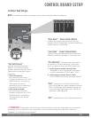
STEP 3
a.
Turn ON the main facility breaker
b.
Verify that all three (3) LEDs are
illuminated at the “Power Box”.
c.
Turn the “Battery Switch” ON.
At the Control Board:
d.
Connect the Power Harness and verify
the “POWER” LED is illuminated solid.
! TECHNICAL TIP: If the “Power” LED is
flashing or any of the 3 LEDs on the
“Power Box” are not illuminated, refer
to the Troubleshooting pages.
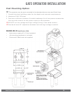
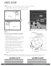
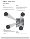
STEP 1
At the “Power Box”:
a.
Set the “Voltage Selector” according
to the supply voltage (115V or 230V).
b.
Turn the “AC Power” switch ON