


VIKING TECHNICAL SUPPORT 1.800.908.0884
20
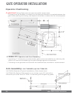
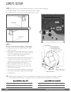
LIMITS SETUP
Tip: Referring to Step 2b. The “Cam Holder” contains four (4) Guide Pin holes to allow
for proper positioning, if required, due to an alternative operator orientation.
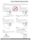
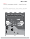
STEP 2
At the “Limit Cam & Holder” assembly:
a.
Loosen screws on both of the “Limit
Switch Cams”.
b.
With the Articulating Arm and “Clutch”
installed, insure that the “Clutch Guide
Pin” is seated into one of the four
holes on the “Cam Holder”.
c.
Move the gate manually to the desired
closed limit position and adjust the
nearest Limit Switch Cam to actuate
the corresponding limit switch.
d.
Slight tighten the Limit Cam Screw.
e.
Repeat Step 2c & 2d for the desired
open limit position.
f.
Run the 2 full cycles before confirming
your limit settings. Adjust accordingly
if required.
1b
1a
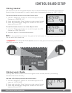
STEP 1 Connect the “Limit Switch Harness” to the Control Board.
a.
“OPEN RIGHT” Connector if the gate opens Right.
b.
“OPEN LEFT” Connector if the gate opens Left.
1
Gate OPENS to the LEFT
Left Limit Switch = Closed Limit
Right Limit Switch = Open Limit
Gate OPENS to the RIGHT
Left Limit Switch = Open Limit
Right Limit Switch = Closed Limit