


VIKING TECHNICAL SUPPORT 1.800.908.0884
17
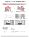
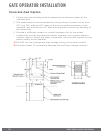
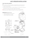
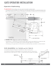
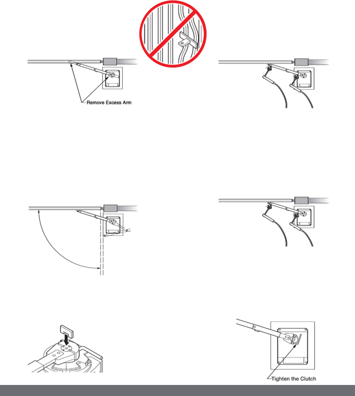
GATE OPERATOR INSTALLATION
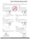
STEP 1
Install the Clutch and cut the
Arm Assembly to achieve
the desired dimensions for
“D” and “E” according to the
formulas provided on page 16.
STEP 2
With the gate at the closed,
install the Arm Assembly.
Check that the dimensions
correspond accordingly to the
formulas provided on page 16.
! IMPORTANT: When attaching the Arm Assembly to the gate, if the “Gate Bracket” is not
welded to a frame member that runs the full length of the gate, the operator may damage
the gate. Do not attach the Gate Bracket to only a few pickets.
! TIP: Leave some additional material
when cutting the Arm Assembly to
allow for adjustment.
! TIP: Use C-clamps or tack-weld the Arm
assembly in place until Step 3 has been
completed.
STEP 3
With the Clutch installed and released,
manually move the gate to both limits.
Verify the following:
1.
The gate reaches the desired limits.
2.
The Arm does not bind at any point.
STEP 4
Once satisfied with the installation and
movement of the gate, weld the arm
pieces securely. Paint the Arm to protect
against rusting.
STEP 5
Rotate the Clutch until it lines up with the
notches on top of the Output Shaft and
insert the Clutch Key.
STEP 6
Verify the Clutch is adjusted properly.
•
Both sides adjusted evenly.
•
Handle is locked, by hand, and
positioned horizontally at 0°.
With the Clutch Key removed, the
Clutch should not slip with moderate
force applied to the gate.