


VIKING TECHNICAL SUPPORT 1.800.908.0884
2
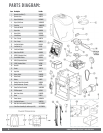
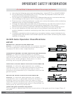
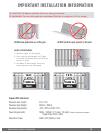
PARTS DIAGRAM:
Item Description Part No.
1 Operator Cover Bolt (2) VASWCB
2 Operator Cover VNXF1CV
3 Output Shaft Knob DWOUK10
4 Output Shaft Cover VNXSWOSC
5 Clutch Key VAWRCK20
6 Clutch and Handle DWCL20
7 Output Arm DWAR20
8 Output Shaft DWOP20
9 Control Board VFLEXPCB
10 Fuse - 15 amp VNXF15A
11 Fuse - 4 amp VNXF4A
12 Limit Switch Holder DWLH10
13 Limit Switch (2) DULS10
14 Limit Cam & Holder DWLC10
15 Worm Gear #70 10:1 DWGB70
16 41B30 3/4 Sprocket (Gear) VASP3034
17 Chain #40x46 Pitches DWCA10
18 41B10 3/4 Sprocket (Motor) VASP1034
19 24V DC Gearhead Motor VAF1MO
20 Brush Kit VAMBK
21 Chassis VNXF1CH
22 Loop Rack VA-LR
23 Battery Switch DUMRS10
24 Motor Switch DUMRS10
25 Battery DUBA12
26 Modular Power Box Assembly VNXMPB
27 Toroid Transformer - 10 amp DUTT10
28 Power Box Panel Assembly VNXUPBPA
29 120V Receptacle VA120PL
30 Main Power Switch DUMRS10
31 Alarm DUAL10
32 Power Harness VNXSWPH
33 Limit Switch Harness VNXF1LSH
34 Multi-Part Arm Assembly (Standard) VA-F1ARM20
Option
Swivel Arm Assembly (for inclines up to 10°) VA-F1SWL20