


VIKING TECHNICAL SUPPORT 1.800.908.0884
30
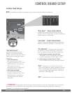
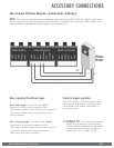
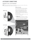
ACCESSORY CONNECTIONS
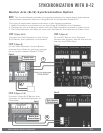
! TECHNICAL TIP: For more information
regarding accessory connections
and terminal functions, refer to
“Appendix (A)” on pages 42-43.
See “Appendix (B)” on page 44 for
connecting common radio receiver
models.
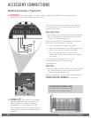
For maximum reception range:
Locate the radio antenna to
the top of the gate column.
COM
N.O.
(-)
(+)
Radio Receiver (Typical)
!
IMPORTANT: The Hold Open “Timer” setting (page 24) affects how the gate will
respond to the radio receiver command.
The control board provides two modes
of operation that a radio receiver can
control the gate:
Open-Stop-Close
1.
By having the radio receiver connected
as illustrated and with the Hold Open
Timer OFF (see page 24):
Every command of the radio transmitter
will control the gate as follows:
a.
First command opens the gate,
b.
Second command stops the gate and
c.
Third command closes the gate
d.
Any subsequent commands will
continue in the same order to control
the gate.
This type of configuration is not
recommended for commercial
installations.
Open Only
2.
By having the radio receiver connected
as illustrated and with the Hold Open
Timer ON (see page 24):
Each command of the radio transmitter is
ALWAYS AN OPEN COMMAND to the gate.