


VIKING TECHNICAL SUPPORT 1.800.908.0884
33
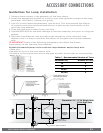
Guidelines for Loop Installation
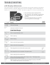
Table C - Recommended Number of Turns
Perimeter (ft.) Number of Turns
10 5
20 4
30-40 3
50-100 2
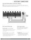
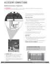
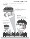
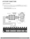
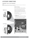
ACCESSORY CONNECTIONS
1.
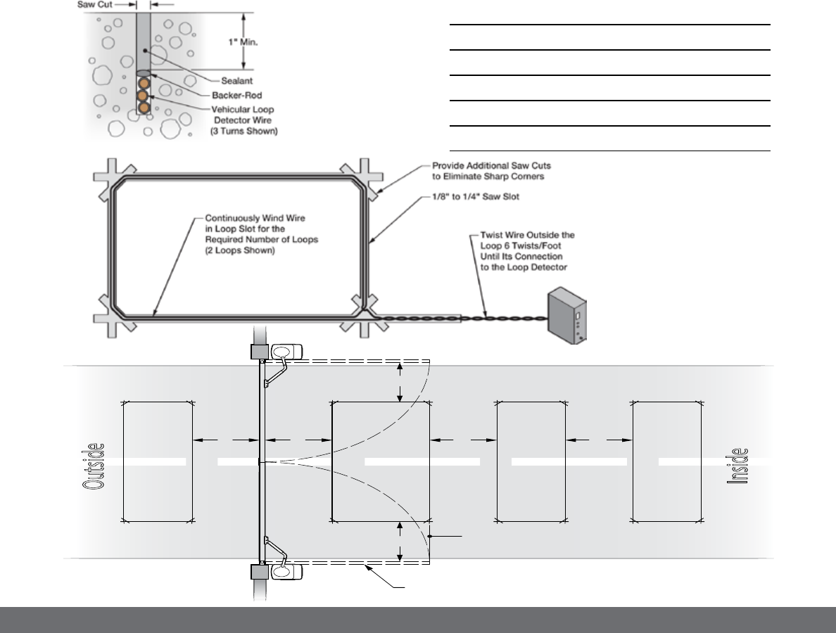
Prevent sharp corners in the geometry of the loop sensor.
2.
Install the appropriate number of turns for your loop geometry based on the loop
perimeter. Use Table C (below) as a guide.
3.
Use XLP (cross-linked-polyethylene) type of wire. This wire reduces the effects
of moisture and other environmental events in altering the functionality of the
vehicular loop detector.
4.
Twist the lead wire at least 6 turns per foot.
5.
Use BACKER-ROD to minimize damage to the loop detector wire prior to using the
sealant.
6.
Place the loop detector wire and adjust the sensitivity of the vehicular loop
detector unit in a way to minimize the effects of the gate over the loop detector
wire.
! IMPORTANT! Some of the following parameters may affect the proper
functionality of the vehicular loop detector.
Consult the manufacturer of the vehicular loop detector and/or loop wire.
•Gatesize
•Numberofturnsintheloopsensorwire
•Distanceoftheloopsensorwiretothegateateitherattheopenorcloseposition
5'
5' 5'
AA
5'
Gate in Open Position
Inside
Reopen
Loop
Center
Loop
Outside
Reopen
Loop
Exit
Loop
Make Even
with Open Gate
Dimension “A” - 5’ for Single Gate
6’ for Dual Gate