


42
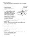
7) Remove the allen head cap screws securing the evaporator to the lower bearing
housing.
8) Raise the evaporator up to access the lower housing.
9) Remove the O-ring and mechanical seal from the housing. If only replacing mechanical
seal, proceed to step 12).
WARNING
To help prevent water leaks, be careful not to damage the surfaces of the
O-ring or mechanical seal.
6b. Lower Housing
10) Remove the bolts securing the housing to the gear motor and remove the housing from
the gear motor. If inspection of the upper bearing inside the extruding head (see "F. 1.
Upper Bearing Wear Check") indicates that it is out of tolerance, replace both it and the
bearing inside the lower housing.
Note: Replacing the bearing requires a bearing press adaptor. If one is not available,
replace the whole extruding head and housing.
11) Mount the lower housing on the gear motor.
12) Install the O-ring and lower part of mechanical seal on the lower housing.
13 ) Lower the evaporator down and secure it to the lower housing.
14) Install the auger assembly with the upper part of the mechanical seal attached.
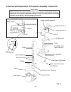
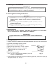
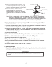
15) Replace the removed parts in the reverse order of which they were removed. When
replacing the spout, make sure that the drip bracket is in the channel and that safety
bracket B is behind safety bracket A. See Fig. 1.
16) Replace the panels in their correct positions.
17) Plug the unit back in.
7. Removal and Replacement of Gear Motor
1) Drain the water from the evaporator by using the ush switch.
2) Unplug the unit from the electrical outlet.
3) Remove the panels.
4) Remove the thumbscrews and take off the spout assembly from the evaporator.
5) Remove the bolts securing the lower housing to the gear motor. Lift the evaporator up
slightly.
6) Remove the bolts securing the gear motor.
7) Remove the wiring from the gear motor, then remove the gear motor.
8) Remove the barrier, gear motor bracket and coupling-spline from the old gear motor
and place on the new gear motor. Apply silicone over barrier screws.
9) Replace the removed parts in the reverse order of which they were removed. When
replacing the spout, make sure that the drip bracket is in the channel and that safety
bracket B is behind safety bracket A. See Fig. 1.