


27
IV. Service Diagnosis
A. Diagnostic Procedure
This diagnostic procedure is a sequence check that allows you to diagnose the electrical
system and components under normal operating conditions of 70°F or warmer air and
50°F or warmer water temperatures. Before proceeding, check for correct installation,
proper voltage per unit nameplate and adequate water supply.
1) Unplug the unit from the electrical outlet and access the control panel.
2) Plug the unit back in. Make sure the ush switch is in the ICE position, then place the
power switch in the ON position.
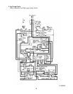
3) Fill Cycle – The water valve energizes. The reservoir begins to ll and the lower oat
switch closes. Nothing occurs at this time. The reservoir continues to ll and the upper
oat switch closes, energizng the water control relay. When the water control relay
energizes, the inlet water valve de-energizes and the low water safety circuit closes to
the timer board. Diagnosis: Check that the water valve lls the reservoir. If not, check
for clogged water lters, clogged water valve screen, power supply to the unit, power
circuit to the water valve (power switch, high pressure switch, transformer, safety switch,
safety relay contacts, fuse, bin control, ush switch, ush relay, ush relay contacts, oat
switch, water control relay contacts), and the coil on the water valve.
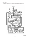
3) Ice Purge Cycle – (short cycle protection) The gear motor and the gear motor protect
relay energize, and the 60 second compressor short cycle protection timer starts.
Diagnosis: Check that the gear motor starts. If not, check the low water safety circuit
on terminals 3 and 4 on the timer board, check for 120 volts on the gear motor relay
terminal 8 on the timer board, check the gear motor fuse, thermal protector, and gear
motor windings. If the gear motor starts but the auger does not turn: check the gear
motor coupling between the auger and the gear motor. If the compressor starts the
same time the gear motor starts: Check the compressor relay on the timer board (the
black relay on the timer board is the compressor relay).
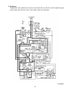
4) Freeze Cycle – The compressor and fan motor energize, the gear motor, gear motor
protect relay, ush switch relay, and the water control relay remain energized. Ice
production begins 4 to 6 minutes after the compressor and fan motor start depending
on ambient and water conditions. Diagnosis: Check that the compressor and fan
motor are running. If not, check for 120 volts on the compressor relay terminal 4 on the
timer board (the black relay on the timer board is the compressor relay), check for 120
volts on the gear motor protect relay, check gear motor relay contacts 4 and 6, check
voltage on the compressor terminals, check the internal overload (motor protector), the
compressor capacitors, and voltage to the fan motor and fan capacitor.