


8 GTO 4000XLS Instruction Manual © 01.10.12
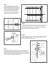
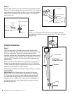
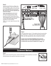
Step 5
Position the operator rear mount between post pivot bracket.
Place a
1
/2” bushing above the rear mount and a
3
/16” bushing
under the rear mount. Align the hole in rear mount, bushings
and post pivot bracket and secure with the 3
1
/2” clevis pin
and hair pin clip.
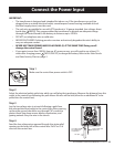
Step 6
Place a
3
/16” bushing under the front mount and attach the
gate bracket to the front mount using the 1
3
/4” clevis pin and
hairpin clip.
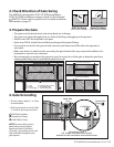
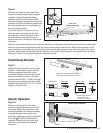
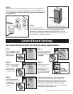
Check Clearance
Step 7
Open the gate to the desired open position. Position the
operator so that the gate bracket rests against the gate along
the level scribed line. Check the clearance between the
operator and the gate. The operator should only make contact
with the gate at the gate bracket. There should be a minimum
clearance of 2” between the widest part of the operator arm
and the gate.
When you have achieved the best position for the post pivot
bracket in the open position, insert the
3
/8” x 3
3
/4” bolt and
3
/8”atwasherthroughthealignedholesofthepostbracket
and post pivot bracket to hold it in place.
Clamp the gate bracket to the gate using c-clamps or another
type of clamp.
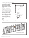
IMPORTANT: While determining the position of the post
pivot bracket, be sure that the position allows for minimum
2“ of clearance between the gate and the operator in both
the open and closed positions. This clearance will give the
operator the most ecient leverage point for opening and
closing the gate and, more importantly, provides the least
possible pinch area.
Operator
3/8” x 3-1/2” Clevis Pin
3/8” x 1/2” Delrin Bushing
3/8” x 3/16” Delrin Bushing
under rear mount
Hairpin Clip
3/8” x 1-3/4” Clevis Pin
Hairpin Clip
Gate Bracket
Front Mount
3/8” x 3/16” Delrin Bushing
under front mount
Clamp
Gate in the
OPEN POSITION
Pinch Area
2" minimum