


Setup
20 313539F
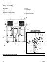
8. Connect heated hose
NOTE:
See Heated Hose manual 309572 for detailed instruc-
tions on connecting heated hoses.
NOTE:
If spraying at a ratio other than 1:1, an E24 may occur.
Size hoses and mix chamber appropriately to avoid
pressure imbalance.
a. Turn main power OFF .
b. Assemble heated hose sections, FTS, and whip
hose.
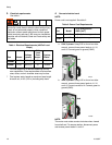
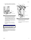
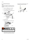
c. Connect A and B hoses to A and B outlets on
Reactor fluid manifold (FM). Hoses are color
coded: red for component A (ISO), blue for com-
ponent B (RES). Fittings are sized to prevent
connection errors.
NOTE:
Manifold hose adapters (N, P) allow use of 1/4 in. and
3/8 in. ID fluid hoses. To use 1/2 in. (13 mm) ID fluid
hoses, remove adapters from fluid manifold and install
as needed to connect whip hose.
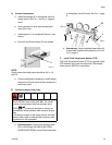
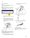
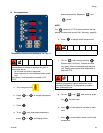
d. Connect cables (Y). Connect electrical connec-
tors (V). Be sure cables have slack when hose
bends. Wrap cable and electrical connections
with electrical tape.
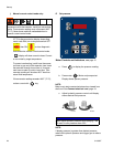
9. Close gun fluid manifold valves A and B
10. Connect whip hose to gun fluid manifold
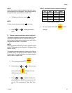
11. Pressure check hose
See hose manual. Pressure check for leaks. If no leaks,
wrap hose and electrical connections to protect from
damage.
NOTICE
The fluid temperature sensor (C) and whip hose (D)
must be used with heated hose, see page 19. Hose
length, including whip hose, must be 60 ft (18.3 m)
minimum.
FM
A
B
ti9878a
N
P
ti9881a
V
Y
ti2411a
ti2417a
Do not connect manifold to gun.