


Component Identification
10 313539F
Component Identification
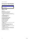
Reactor H-VR
Key for FIG. 3
BA Component A Pressure Relief Outlet
BB Component B Pressure Relief Outlet
EC Heated Hose Electrical Connector
EM Electric Motor, Fan, and Belt Drive (behind shroud)
FA Component A Fluid Manifold Inlet (on left side of manifold
block)
FB Component B Fluid Manifold Inlet
FH Fluid Heater (behind shroud)
FM Reactor Fluid Manifold
FV Fluid Inlet Valve (B side shown)
GA Component A Outlet Pressure Gauge
GB Component B Outlet Pressure Gauge
HA Component A Hose Connection
HB Component B Hose Connection
HC Hydraulic Pressure Control
HP Hydraulic Pressure Gauge
LR ISO Lube Pump Reservoir
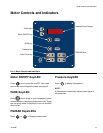
MC Motor Control Display
MP Main Power Switch
OP Overpressure Rupture Disk Assembly (on rear of A and B
pumps)
RS Red Stop Button
SA Component A PRESSURE RELIEF/SPRAY Valve
SB Component B PRESSURE RELIEF/SPRAY Valve
SC Fluid Temperature Sensor Cable
SN Serial Number Plate (one inside cabinet, one on right side
of cabinet)
SR Electrical Cord Strain Relief
TA Component A Pressure Transducer (behind gauge GA)
TB Component B Pressure Transducer (behind gauge GB)
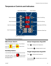
TC Temperature Control Display
TD Oil Cooler
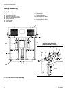
VR Pump Assembly (see page 12)
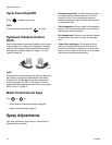
NOTICE
To prevent damage to soft key buttons, do not press
the buttons with sharp objects such as pens, plastic
cards, or fingernails.