


Setup
313539F 19
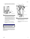
5. Connect feed pumps
a. Install feed pumps (K) in component A and B
supply drums. See F
IG. 1 and FIG. 2, pages 8
and 9.
b. Seal component A drum and use desiccant
dryer (M) in vent.
c. Install agitator (L) in component B drum, if nec-
essary.
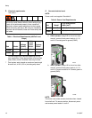
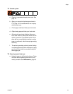
d. Ensure A and B inlet valves (FV) are closed.
NOTE:
Supply hoses from feed pumps should be 3/4 in. (19
mm) ID.
e. Connect and tighten component A and B supply
hose to the 3/4 npt(f) swivel on the component A
and B inlet valve.
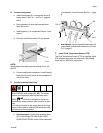
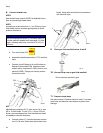
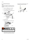
6. Connect pressure relief lines
a. Recommended: Connect high pressure hose
(R) to relief fittings (BA, BB) of both PRES-
SURE RELIEF/SPRAY valves, Route hose back
to component A and B drums. See F
IG. 1, page
8.
b. Alternatively: Secure supplied bleed tubes (N)
in grounded, sealed waste containers (H). See
F
IG. 2, page 9.
7. Install Fluid Temperature Sensor (FTS)
The Fluid Temperature Sensor (FTS) is supplied. Install
FTS between main hose and whip hose. See Heated
Hose manual 309572 for instructions.
Do not install shutoffs downstream of the PRESSURE
RELIEF/SPRAY valve outlets (BA, BB). The valves
function as overpressure relief valves when set to
SPRAY . Lines must be open so valves can
automatically relieve pressure when machine is oper-
ating.
If circulating fluid back to the supply drums, use high
pressure hose rated to withstand the maximum work-
ing pressure of this equipment.
FV
ti10971a
ti9880a
BA
BB
R
R
SB
SA