


Models
2 313539F
Contents
Models . . . . . . . . . . . . . . . . . . . . . . . . . . . . . . . . . . . 2
Supplied Manuals . . . . . . . . . . . . . . . . . . . . . . . . . . 3
Related Manuals . . . . . . . . . . . . . . . . . . . . . . . . . . . 3
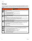
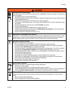
Warnings . . . . . . . . . . . . . . . . . . . . . . . . . . . . . . . . . 4
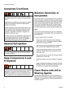
Isocyanate Conditions . . . . . . . . . . . . . . . . . . . . . . 6
Material Self-ignition . . . . . . . . . . . . . . . . . . . . . . . . 6
Keep Components A and B Separate . . . . . . . . . . 6
Moisture Sensitivity of Isocyanates . . . . . . . . . . . . 6
Foam Resins with 245 fa Blowing Agents . . . . . . . 6
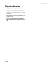
Changing Materials . . . . . . . . . . . . . . . . . . . . . . . . . 7
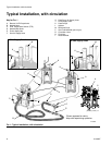
Typical Installation, with circulation . . . . . . . . . . . 8
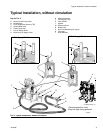
Typical Installation, without circulation . . . . . . . . 9
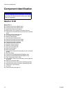
Component Identification . . . . . . . . . . . . . . . . . . . 10
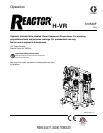
Reactor H-VR . . . . . . . . . . . . . . . . . . . . . . . . . . 10
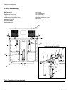
Pump Assembly . . . . . . . . . . . . . . . . . . . . . . . . 12
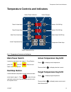
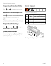
Temperature Controls and Indicators . . . . . . . . . 13
Main Power Switch . . . . . . . . . . . . . . . . . . . . . . 13
Red Stop Button . . . . . . . . . . . . . . . . . . . . . . . . 13
Actual Temperature Key/LED . . . . . . . . . . . . . . 13
Target Temperature Key/LED . . . . . . . . . . . . . . 13
Temperature Scale Keys/LEDs . . . . . . . . . . . . . 14
Heater Zone On/Off Keys/LEDs . . . . . . . . . . . . 14
Temperature Arrow Keys . . . . . . . . . . . . . . . . . . 14
Temperature Displays . . . . . . . . . . . . . . . . . . . . 14
Circuit Breakers . . . . . . . . . . . . . . . . . . . . . . . . . 14
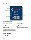
Motor Controls and Indicators . . . . . . . . . . . . . . . 15
Motor ON/OFF Key/LED . . . . . . . . . . . . . . . . . . 15
PARK Key/LED . . . . . . . . . . . . . . . . . . . . . . . . . 15
PSI/BAR Keys/LEDs . . . . . . . . . . . . . . . . . . . . . 15
Pressure Key/LED . . . . . . . . . . . . . . . . . . . . . . . 15
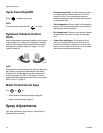
Cycle Count Key/LED . . . . . . . . . . . . . . . . . . . . 16
Hydraulic Pressure Control Knob . . . . . . . . . . . 16
Motor Control Arrow Keys . . . . . . . . . . . . . . . . . 16
Spray Adjustments . . . . . . . . . . . . . . . . . . . . . . . . 16
Setup . . . . . . . . . . . . . . . . . . . . . . . . . . . . . . . . . . . . 17
Startup . . . . . . . . . . . . . . . . . . . . . . . . . . . . . . . . . . 22
Spraying . . . . . . . . . . . . . . . . . . . . . . . . . . . . . . . . . 28
Standby . . . . . . . . . . . . . . . . . . . . . . . . . . . . . . . . . . 30
Shutdown . . . . . . . . . . . . . . . . . . . . . . . . . . . . . . . . 30
Pressure Relief Procedure . . . . . . . . . . . . . . . . . . 31
Fluid Circulation . . . . . . . . . . . . . . . . . . . . . . . . . . . 32
Circulation Through Reactor . . . . . . . . . . . . . . . 32
Circulation Through Gun Manifold . . . . . . . . . . . 33
Diagnostic Codes . . . . . . . . . . . . . . . . . . . . . . . . . . 34
Temperature Control Diagnostic Codes . . . . . . . 34
Motor Control Diagnostic Codes . . . . . . . . . . . . 35
Maintenance . . . . . . . . . . . . . . . . . . . . . . . . . . . . . . 36
Fluid Inlet Strainer Screen . . . . . . . . . . . . . . . . . . 37
Flushing . . . . . . . . . . . . . . . . . . . . . . . . . . . . . . . . . 38
Dimensions . . . . . . . . . . . . . . . . . . . . . . . . . . . . . . . 39
Technical Data . . . . . . . . . . . . . . . . . . . . . . . . . . . . 40
Performance Charts . . . . . . . . . . . . . . . . . . . . . . . . 41
Graco Standard Warranty . . . . . . . . . . . . . . . . . . . 44
Graco Information . . . . . . . . . . . . . . . . . . . . . . . . . 44
Models
* Full load amps with all devices operating at maximum capabilities. Fuse requirements at various flow rates and mix chamber
sizes may be less.
◆ Maximum flow rate given for 60 Hz operation. For 50 Hz operation, maximum flow rate is 5/6 of 60 Hz maximum flow.
Part,
Series
Full Load
Peak Amps*
Per Phase
Voltage
(phase)
System
Watts†
Primary
Heater
Watts
Max Flow
Rate◆
lb/min
(kg/min)
Approximate
Output per
Cycle (A+B)
gal. (liter)
Hydraulic
Pressure
Ratio
Maximum Fluid
Working Pressure
psi (MPa, bar)
256886 71 230V (3) 26,600 15,300 30 (13.6) Variable Variable 3500 (24.1, 241)
256887 41 400V (3) 26,600 15,300 30 (13.6) Variable Variable 3500 (24.1, 241)