


6050-065-L-11-08
31
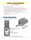
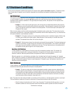
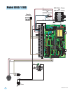
1
Motor
2
Motor
3
Neutral
4
24VAC
5
Limit
6
Spare
7
Limit
8
COM
DC MOTOR NEGATIVE OUTPUT
DC MOTOR POSITIVE OUTPUT
BATTERY NEGATIVE INPUT
BATTERY POSITIVE INPUT
24 VAC COMMON
24 VAC INPUT
ACTIVATION OUTPUT
RADIO POWER
OPEN INPUT
COMMON
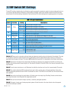
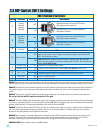
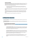
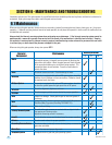
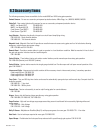
5.3 DIP-Switch Settings
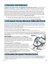
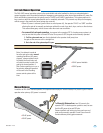
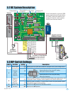
5.2 DC System Description
Switch Function Setting Description
Power Failure
Operating Modes
Restored
AC Power
Operator
Response
OFF
ON
OFF
OFF
Operator Type
Manual input from 2340 board needed to open gate when a power outage occurs.
Do Not Adjust Do Not Adjust
Timer needs to
be adjusted.
Charging LED
Not Used
1
2
3
4
5-8
Gate will automatically open when a power outage occurs.
OFF
ON
When AC power is restored, a manual input (push button, loop, radio receiver, etc.)
is required to return the gate to normal operation from 2340 or 4502 board.
When AC power is restored, a 1-second pulse is sent to the gate operator input to
automatically restore normal operation.
Must be in the OFF position for the 6050 and 6100.
Must be in the OFF position.
2340
Gate will automatically or manually OPEN
and stay open during an AC power failure.
DIP-Switch 3 setting will determine how
operator will return to normal operation
once AC power has been restored.
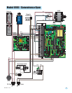
–
+
12 V
3 Amp/Hr
–
+
12 V
3 Amp/Hr
Batteries
Secondary Operator
2340 Board Terminal
Secondary Operator
Terminal
DC ON/OFF
Power Switch
Red
Red
Green
Purple
White
Black
Red/White
Red/White
DC Motor
Black/White
To Primary or Single Operator
Green to Main Terminal #11
Purple to Main Terminal #7
White to Main Terminal #20
See
previous
page.
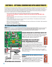
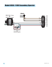
Changes
Arm’s
Opening
Direction
OFF
ON
8
7
4
DIP-Switches
2340 Board Terminal
Timer
Opening direction of arm using OFF setting.
Gate opens counter-clockwise.
Opening direction of arm using ON setting.
Gate opens clockwise.