


6050-065-L-11-08
11
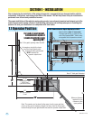
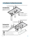
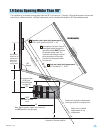
1.2 Post Mount or Pad Mount Base Assembly
Hardware for Pad Mount:
Pad Support Base
Post Support Base
(6) 1 inch bolts, lockwashers and nuts for support legs.
(2) 1 inch bolts and nuts for support plate.
(2) 1 1/2 inch bolts and nuts. For support plate.
(3) Non-slip nuts. For existing threaded studs on bottom of operator.
(2) 1 1/2” bolts through the main
gear bracket mounting holes.
(2) 1 1/2” bolts through the main
gear bracket mounting holes.
(2) 1” bolts through the main gear bracket mounting holes.
(2) 1” bolts through the main
gear bracket mounting holes.
Hardware for Post Mount:
(2) 1 1/2 inch bolts. For support plate.
(2) 1 inch bolts. For support plate.
(3) Non-slip nuts. For existing threaded
studs on bottom of operator.
Remove the cover from the
operator and GENTLY place
the operator on its side before
attaching the pad base.
Screw the posts to the support
plate and mount into concrete
BEFORE attaching the operator.
Bottom of Operator
Bottom of Operator
Support
Plate
Support
Plate
Left Support Leg
1
” Bolts
Right
S
upport
Leg