


6050-065-L-11-08
13
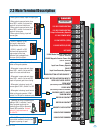
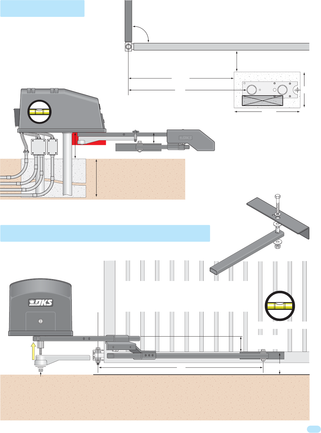
Arm
Rotation Area
Closed Gate
3”
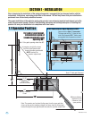
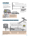
1.5 Post Mount
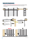
1.6 Arm and Gate Bracket Installation
10”
18.5”
34”
6”
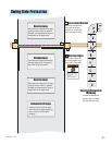
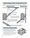
Do not insert the locking pin or padlock
into the crank arm. It will be installed
after arms have been adjusted.
Do not secure the elbow assembly
to the arms until the arms have
been adjusted. (See next page).
Mount the post base into the concrete
before installing the operator.
The post mount installation will allow
the operator to be mounted low enough
to attach the gate bracket to the lower
gate rail if desired.
Adjust the locknut on the crank power
arm so that it is snug against the
washer, but will still allow the crank arm
to rotate with little force. This is the
operator’s manual release option when
the crank arm is unlocked.
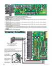
Assemble arms as shown with the gate in the closed
position. The elbow assembly’s flange MUST be on the
opposite side of the gate in the closed position. This is
the physical stop used to set the open and close limits.
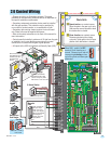
Concrete
Position
Gate Rail
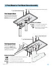
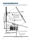
These measurements will work for standard or
convenience open models from 1.1 layout on page 10 ONLY.
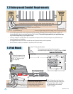
Run all conduit on the opposite
side of the open gate.
Install gate
bracket to gate.
30” Crank Arm
60” Connecting Arm
Flange
Crank Power Arm
Elbow
Assembly
Top of Crank Arm
Point arms towards
gate bracket.
Gate Hinge Pivot Point
Arms MUST be level.
This distance can vary (6” minimum).
Varies
60” C
onnecting Arm
G
a
te
Bracket
Note: 2” thick gate Illustrated.
25.25”
Conduit
29”
Post Base
Open Gate
Closed Gate
90°
Depth of the concrete pad is
determined by soil conditions and
local building codes. Reinforced
concrete recommended.
Gate Bracket Height
3”
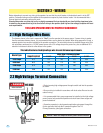
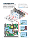
Low
Volt
High
Volt
Interconnection
Cable
Operator MUST
be level.