


6050-065-L-11-08
19
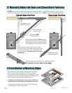
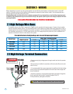
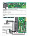
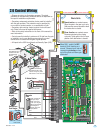
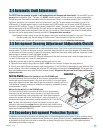
2.6 Control Wiring
Radio Receiver
Limited to 250 ma.
Open direction non-contact sensor.
Stops the gate in the open cycle only.
Gate resumes normal operation when
the obstruction is cleared.
Close direction non-contact sensor.
Reverses gate during the closing
cycle only. Holds gate in the full open
position until obstruction is cleared.
Power (24 Volt DC)
and logic output.
Power is shut off
.5 sec. prior to gate
starting and remains
off while gate is
opening and in the
open position.
Convenience open radio
receiver wiring may differ.
See section 5.1 for more info.
Com
Com
Com
Relay
Red Open
Green Close
White Com
24 Volt
24 V
Com
Com
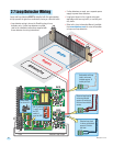
Key Switch
Stand-Alone
Keypad
Stand-Alone
Card Reader
Telephone
Entry
Photo Cells
B
B
AA
A
Note: All stand-alone
and telephone entry
devices must use a
separate power
source.
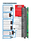
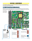
Fire Box
When SW 1, switch 5 is OFF,
terminal 15 will function as a
normal “Reverse Input” and will
reverse the gate during a close
cycle if the photo cell beam gets
obstructed.
1
1
ON
2 3 4 5 6 7 8
SW 1
20
19
18
17
16
15
14
13
12
11
10
9
8
7
6
5
4
3
2
1
NC
NO
POW
E
1
ON
2 3 4 5 6 7 81
ON
2 3 4 5 6 7 8
Magnetic
Lock
3-Button Station
DoorKing ONLY
123456 87
4502
Auxiliary Terminal
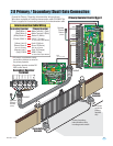
• Diagram at right is for illustration purposes. The actual
placement of the secondary protection devices is dependent on
the specific installation requirements.
• Secondary entrapment protection devices must be installed
with this gate operator. This protection may be provided by
non-contact or contact sensors, or a combination of both.
• Secondary device wiring shows inputs to the circuit board
only. Photo-cells must be supplied with power.
• Refer to the safety instructions in the front of this manual for
more information.
• Controls must be installed a minimum of 10-feet from the gate
or installed in such a way that the person using the control
cannot come in contact with the gate or gate operator.
• All inputs to the 4502 circuit board are Normally Open (N.O.).
SW 1
SW 2
SW 1, switch 3
must be ON.
1
ON
2 3 4 5 6 7 8
SW 1
15
20