


6050-065-L-11-08
22
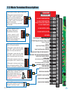
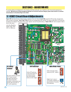
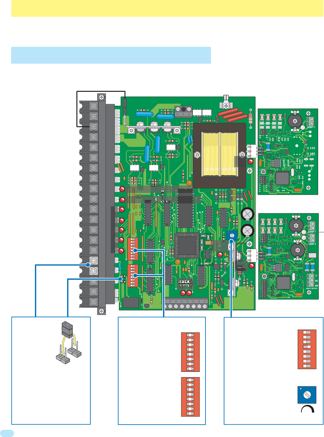
3.1 4502 Circuit Board Adjustments
SECTION 3 - ADJUSTMENTS
The switch settings and adjustments in this chapter should be made after your installation and wiring to the operator(s) is
complete. Whenever any of the programming switches on the circuit board are changed, power must be shut-off, and then
turned back on for the new setting to take effect.
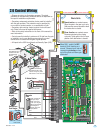
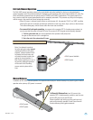
Power LED indicates that low voltage power is applied to the circuit board. Input LEDs should be OFF and will only illuminate
when an input is activated. Pulse 1 and 2 LEDs will blink as the operator(s) are running. They can be either ON or OFF when the
operator(s) are stopped. One pulse LED for each operator used (Primary/Secondary). Tracker LEDs will flash as operator data is
sent to the access
controller (DoorKing
models 1833, 1835,
1837 or 1838 only).
Auto-close timer (when
turned on) SW 1, switch 4.
Adjust from 1 second
(full counter clockwise) to
approximately 23 seconds
(full clockwise).
Dry relay contacts (terminals
16-17) can be set for
Normally Open (NO) or
Normally Closed (NC)
operation by placing the relay
shorting bar on the N.O. or
N.C. pins respectively.
1
1
ON
2 3 4 5 6 7 8
SW 1
Loop Detector
Loop Detector
123
9410
EXIT
SHADOW SHADOW OUTPUTREVERSE
9409
Auto-Close Timer
Dry Relay
Contact
20
19
18
17
16
15
14
13
12
11
10
9
8
7
6
5
4
3
2
1
NC
NO
1
ON
2 3 4 5 6 7 81
ON
2 3 4 5 6 7 8
NC
NO
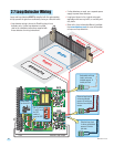
Set the DIP-switches
on the circuit board to
the desired setting.
See switch-setting
charts on next 2 pages.
1
ON
2 3 4 5 6 7 8 1
ON
2 3 4 5 6 7 8
SW 1
SW 1
SW 2
SW 2
DIP-Switches
Tracker
LEDs
Power
LED
Input LEDs
Pulse 1 LED Primary Operator
Pulse 2 LED Secondary Operator
Loop
LED
Board
Ground
Board
Power
Loop
LED
4502