


6050-065-L-11-08
10
SECTION 1 - INSTALLATION
Prior to beginning the installation of the swing gate operator, we suggest that you become familiar with the
instructions, illustrations, and wiring guide-lines in this manual. This will help insure that your installation is
performed in an efficient and professional manner.
The proper installation of the vehicular swing gate operator is an extremely important and integral part of the
overall access control system. Check all local building ordinances and building codes prior to installing this
operator. Be sure your installation is in compliance with local codes.
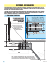
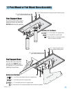
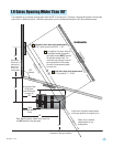
1.1 Operator Position
35”
90°
90°
90°
Note: 2” thick gate Illustrated.
4”
3”
Gate Bracket
An imaginary straight line drawn
from the closed gate bracket
through the open gate bracket
MUST intersect the
operator output shaft.
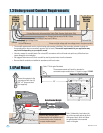
For pad or post mount ,
convenience open or
standard with the gate
opening 90°.
See 1.9 for gate’s opening wider than 90°.
Minimum distance
required for arm
clearance in the
open position.
Note: The operator can be placed further away from the open gate than
shown as long as the imaginary straight line drawn from the closed gate
bracket through the open gate bracket intersects the operator output shaft.
34”
12”
43”
Closed Gate
Open Gate
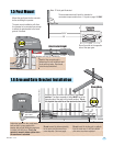
21.25”
Convenience Open
6100 Cover
(See above detail)
Standard Operator
Cover
12”
12”
Closed Gate
Closed Gate
3”
5”
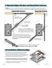
Output shaft is offset 1” from center.
The open gate will be 1” closer on one
side of the operator OR 1” further away
on opposite side of operator as shown.
Operator
Output
Shaft
Open Gate
Open Gate
Centerline
7.25”
6.75”
43”
6100 Convenience Open Operators ONLY:
Operator
Output
Shaft
26”