


Rev J Doc 01-20098 Page 9 of 44
PART 2
SYSTEM INSTALLATION
A. GATE AND PHOTO-SENSOR LAYOUT
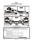
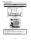
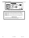
Figure 7. Photo-Sensor Layout.
IMPORTANT NOTE
The installation shown in Figure 7 is a suggested layout using emitters and receivers. Any UL
approved photo-sensors are acceptable, but they must cover the entire length of gate travel to
be effective.
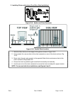
1. Install photo-sensors in three places as shown in Figure 7.
A. Inside-Open Coverage:
Inside the gate, from the gate operator to the gate fully open position.
B Inside-Closed Coverage:
Inside the gate, from the gate operator to the gate fully closed position.
C. Outside-Closed Coverage:
Outside the gate, from the fence edge to the gate fully closed position.
2. For wiring instructions, see Paragraph K, Connecting Input Wiring, below.
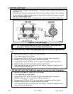
NOTE: If you are installing a Master/Slave system, refer to Series B3 Master/Slave Systems for
additional layout information.