


Rev J Doc 01-20098 Page 13 of 44
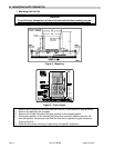
F. SETTING GATE OPEN DIRECTION SWITCHES S2 AND S3
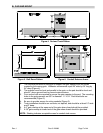
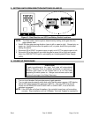
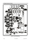
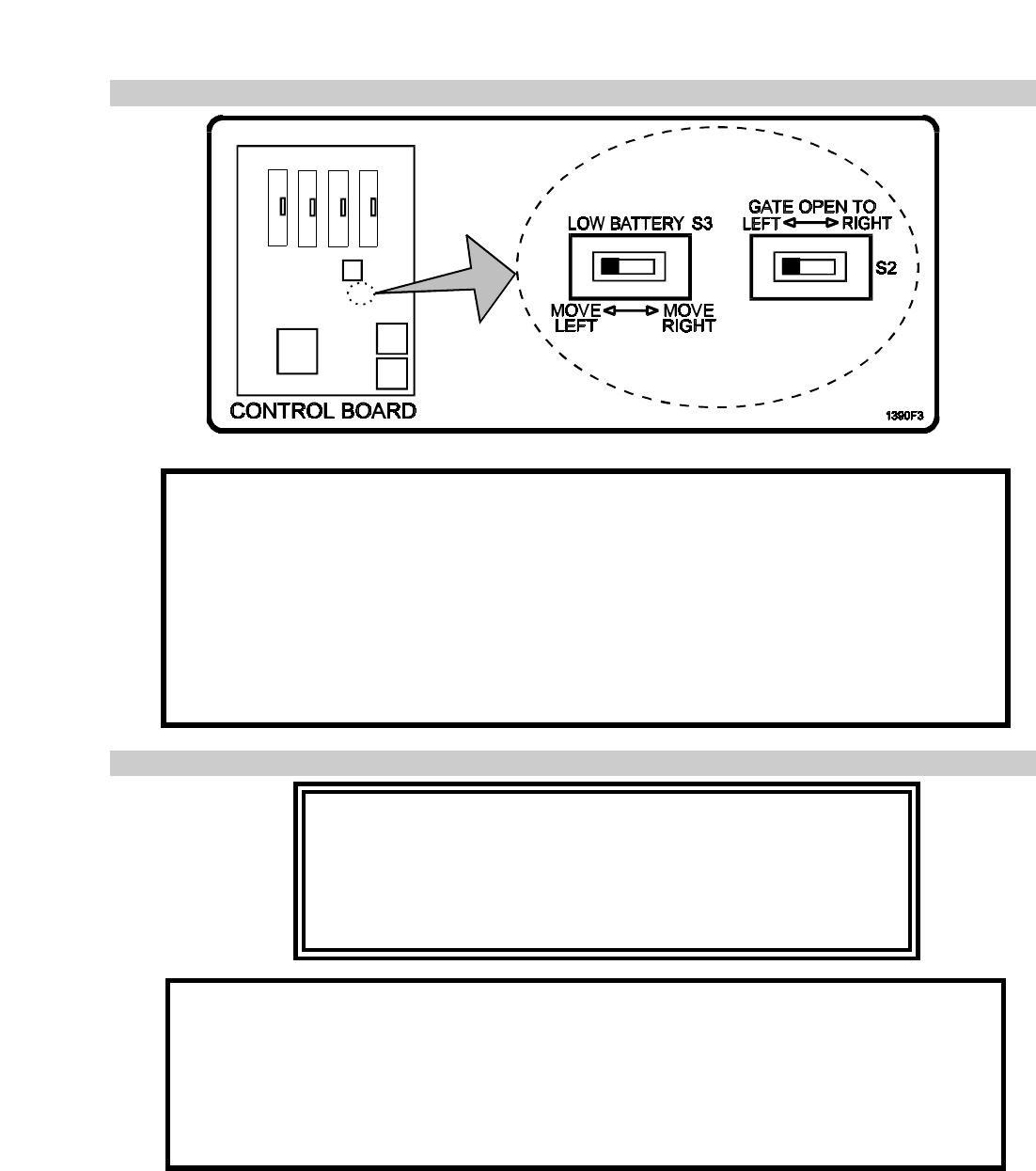
Figure 12. Gate Direction and UPS Low Battery Switch Locations.
NOTE: The Gate motion (left to right) is determined by looking at the gate from the
gate operator side.
• Switch S2 sets gate opening direction (open to left or open to right). Sensed only on
power up, it should be set when the power is off, or power should be cycled after
setting the switch.
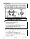
1. Set switch S2 to RIGHT for gate to open to right, or to LEFT for gate to open to left.
2. Set switch S3 to the direction you wish the gate to move (left or right) and remain
when the LOW BATTERY input is activated by an Uninterruptable Power Supply
(UPS).
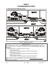
G. POWER UP PROCEDURE
CAUTION
If gate is positioned at the ‘open’ limit, gate will automatically
close if Relcose Timer is enabled and power is switched on.
Position gate either at the closed limit or at no limit when
preparing to switch power on. Always use extreme caution and
follow all warnings in the Safety Summary.
1. Turn on circuit breaker that provides power to gate operator.
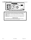
2. Turn on gate operator power switch and verify that the seven-segment LED display
above the keypad sequentially spells out “HELLO”. The only LEDs that should
remain on are MAGLOCK and CLOSE LIMIT or OPEN LIMIT, if one of the limit
switches is engaged.
NOTE: If the LEDs do not follow this pattern, the controller board may not be working
correctly. Stop installation and call LiftMaster Technical Support for assistance.