


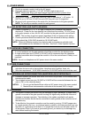
Rev J Doc 01-20098 Page 12 of 44
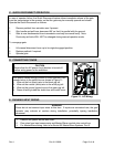
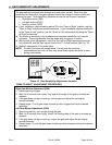
C. QUICK DISCONNECT OPERATION
In case of operator failure, the Quick Disconnect feature allows immediate release of the gate
from the transmission in the operator so that the gate may be manually opened and closed.
Operate the Quick Disconnect as follows:
1. Remove padlock from actuation arm if present.
2. Grip handle and pull lever downward 90° so that it is parallel with the ground.
3. Gate is now disconnected from transmission and may be moved freely. Note:
Previously set limits WILL NOT be changed during manual operation mode.
To re-engage gate:
1. Lift manual disconnect lever up to its original engaged position.
2. Replace padlock if required.
3. Operate gate.
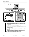
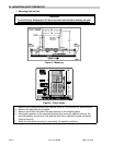
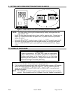
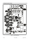
D. CONNECTING POWER
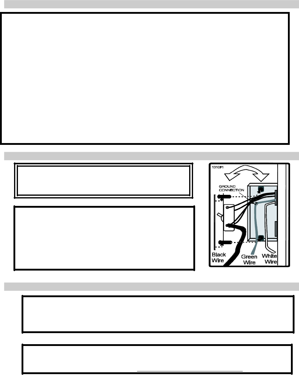
Figure 11. AC Wiring.
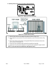
E. RUNNING INPUT WIRING
WARNING
Route but do not connect input wires at this time. If inputs are connected now, the gate
operator may activate at random during installation, potentially injuring installation
personnel.
1. Remove the plastic control box cover.
2. Run wires from input components and Master/Slave conduits into control box.
3. For Master/Slave wiring, refer to for Series X3 Master/Slave Systems, Part 2.
CAUTION
Ensure that the AC power circuit breaker is turned off
before wiring power to the switchbox.
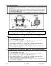
Run power cables through conduit to Gate Operator, then
connect wires to the switch box as shown in Figure 11:
1. Wire nut the hot (black) wire to the black pig tail.
2. Wire nut the neutral (white) wire to the white pig tail.
3. Wire nut the ground (green) wire to the green pig tail.
4. Dress all wiring inside the switch box and install cover.