


Rev J Doc 01-20098 Page 6 of 44
PART 1
SITE
PREPARATION
A. LOCATION AND LAYOUT
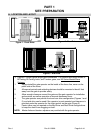
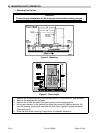
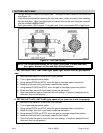
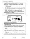
Figure 1. Front Drive.
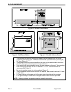
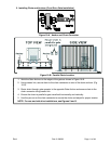
Figure 2. Rear Drive.
Figure 3. Mid Drive.
• Figures 1-3 show typical single gate installations. For location and layout details of
Bi-Parting, Bi-Parting Latch, and Tandem gates, see X3 Series Master/Slave
Systems.
1. Always install the gate operator on the inside of the fence line, never on the
public side of the fence.
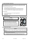
2. All manual controls and activating devices should be mounted at least 6 feet
away from the gate to provide safety.
3. Allow enough clearance around the gate and the gate operator for installation
and services, as well as operation of manual disconnect lever.
4. The gate operator can provide front and rear drive configuration (Figures 1 and
2), and mid drive can be used if the operator is post mounted and clearance is
provided under the operator for the chain anchor on the gate (Figure 3).
5. Center idlers may be required on the Mid Drive and Rear Drive configurations
to keep the chain from dragging on itself.
NOTE: Master links and tension adjusters are provided with the gate operator.