Rev J Doc 01-20098 Page 8 of 44
C. POWER WIRING
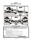
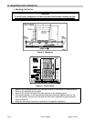
1. Provide a separate conduit stub for the AC power.
2. Each gate operator requires a 115 VAC 20 AMP single phase circuit
NOTE: Master and Slave units each require separate circuits to prevent false
overcurrent faults (see X3 Series Master/Slave Systems).
3. Wiring must comply with the local Electrical Code for operating a
1
/2 HP motor. 12
AWG for up to 300' and 10 AWG for up to 500' long wire runs is suggested.
4. Be sure to pull a ground wire in the conduit for the connection to the gate operator.
NOTE: Do not rely on metallic conduit for earth ground.
D. LOOP DETECTORS AND PHOTO-SENSORS
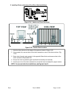
1. A shelf is provided (10" x 11" x 18" high) to support non-LiftMaster loop detector
electronics. Power for the loop detector can come from the auxiliary 115 VAC plugs
in the gate operator or from the 24 VAC provided by the gate operator control board.
NOTE: The auxiliary plugs have power regardless of the unit power switch setting.
2. Conduit provisions should be made for the “loop” wire entrance to the loop detector.
3. Wiring should be 16-24 AWG stranded or 18-24 AWG solid.
NOTE: Optional LiftMaster-supplied loop detector add-on boards are available, both
pre-installed and for installation in the field. See Part 3, Gate Operator Options.
E. TELEPHONE CONNECTION
1. A conduit entrance into the gate operator should be provided for the telephone line.
2. A single twisted pair wire 18 AWG to 24 AWG, will be connected from the telephone
company termination block through the conduit to J9 on the control board. Polarity is not
important.
NOTE: Do not run telephone and AC power wires in the same conduit.
F. OTHER CONNECTIONS
1. Provisions should be made for conduit entrance into the gate operator for external
activation devices such as key switches, telephone entry systems, loops, etc.
2. Wire size requirement: 16-24 AWG stranded or 18-24 AWG solid wire should be used.
G. MASTER/SLAVE INTERCONNECTION (MASTER/SLAVE SYSTEM ONLY)
1. A conduit between the Master and Slave units should be provided for the Master/Slave
interconnection cable.
2. Two shielded twisted pair wire 16 AWG to 24 AWG will be connected between the two
units at TB1 on the controller board.
NOTES: 1. Do not run the Master/Slave cable and AC power wires in the same conduit.
2. Master/Slave interconnection cable should not exceed 3000' in length.
H. GROUNDING
1.
2.
The system contains parts which may be damaged by static discharge. A proper earth
ground connected to the gate operator housing will significantly reduce the chances of
damage or improper operation. The shielding in the cables specified for all remote
sensors and controls should also be connected to earth ground at the controller end of
the cable only.
To be effective, the ground connection must be made by running 12 AWG copper wire
to a good ground point (e.g., an electrical panel, a metallic cold water pipe that runs into
the earth, or a grounding rod at least 10' in length that is driven into the earth) within 12'
of the system. Even if you have a good earth ground, you should try to discharge any
static before handling the boards.


