


6
USER INSTRUCTIONS
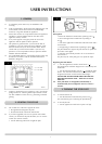
• Remove the ceramic fuel bed components and place to
one side
You must protect floor covers and handle the ceramic logs
with care
5.3 The logs should not require cleaning:
• Do not use a vacuum cleaner or brush to clean the logs
• Remove any large debris by hand
• Make sure no debris blocks the burner ports
5.5 See Section 6 to replace the ceramic logs.
5.6 Use a damp cloth to clean the outer casing of the stove.
The fuel effect and side panels in this stove are made from
Refractory Ceramic Fibre (RCF), a material commonly used
for this stove.
Protective clothing is not required when handling these
articles, but we recommend you follow normal hygiene
rules of not smoking, eating or drinking in the work area
and always wash your hands before eating or drinking.
During installation and servicing a HEPA filtered vacuum is
recommended to remove any dust accumulated in and
around the stove before and after working on it to reduce
RCF fibres. On servicing the stove we recommend any
replaced items are not broken up, but are sealed within
heavy duty polythene bags and labelled as RCF waste.
RCF waste is classed as stable, non-reactive hazardous
waste and may be disposed of at a licensed landfill site.
Excessive exposure to these materials may cause temporary
irritation to eyes, skin and respiratory tract; wash hands
thoroughly after handling the material.
• Open the door as set out in Section 5 above
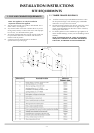
The fuel bed consists of 5 logs and 2 ash panels. The logs
have letters A,B,C,D and E moulded into them for
identification.
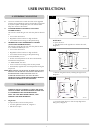
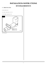
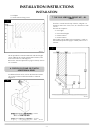
6.1 • Take the rear log A
6. FUEL BED ARRANGEMENT
Advice on Handling and disposal of fire ceramics
6
AR1943
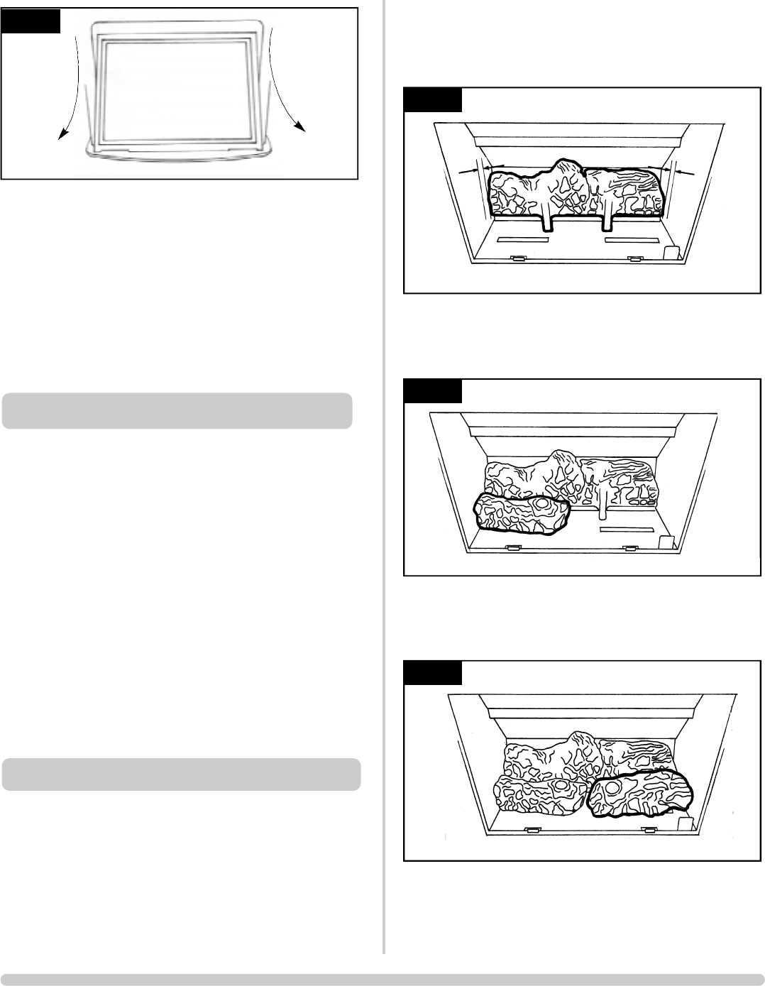
• Place it up against the rear of the fire sitting on the two
flat ledges of the burner. The two legs of the log should sit
between the rear burner ports. See Diagram 7
• Ensure there is an equal gap between the sides of the
firebox at each end of the log
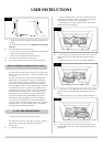
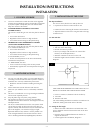
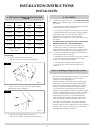
6.2 • Place log B on the left-hand side of the burner with the
location bar on its underside slid into the long slot of the
burner
• Make sure the log is as far left as possible, Diagram 8
6.3 • Place log C on the right-hand side of the burner with the
location bar on its underside slid into the long slot of the
burner.
• Make sure the log is as far right as possible, Diagram 9
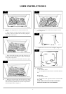
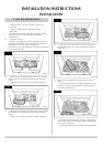
6.4 • Place log D across from the rear log A to log B on the
left-hand side. There are cut-outs in both logs for location,
Diagram 10
AR1612
9
AR1611
8
AR1610
7