


12
INSTALLATION INSTRUCTIONS
INSTALLATION
1.1
Your stove is fitted with a control valve that can be upgraded
to battery powered Remote Control. This upgrade can be fitted
by anyone capable of simple DIY jobs. Your Yeoman dealer
keeps two versions of the remote:
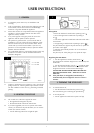
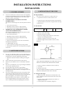
1.2 STANDARD REMOTE CONTROL (Yeoman PART
NUMBER YM-8455)
This remote controls the gas stove after the pilot has been lit
to:
• Turn on the main burner
• Regulate the flame from low to high and back
• Turn off the burner leaving just the pilot burning
1.3 THERMOSTATIC AND TIMER REMOTE CONTROL
(Yeoman PART NUMBER YM-8456)
This remote controls the gas stove after the pilot has been
lit. In ‘MANUAL MODE’ you can:
• Turn on the main burner
• Regulate the flame from low to high and back
• Turn off the burner leaving just the pilot burning
In ‘AUTO MODE’ you can:
• Set the room temperature so the stove automatically
maintains that temperature
In ‘TIMER MODE’ the stove:
• Turns on and off according to the set time periods
• Automatically regulates the room temperature during the
set periods
2.1 For your own and other’s safety, you must install this stove
according to local and national codes of practice. Failure to
install the stove correctly could lead to prosecution:
• Read these instructions before installing and using this
stove.
2.2 All the instructions must be left intact with the user.
2.3 Make sure you install the stove in a sufficiently ventilated
space.
2.4 This stove is intended for use on a governed gas installation
and set to the required pressure.
2.5 Keep all plastic bags away from young children.
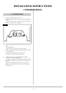
2.6 Do not place any object on or near the stove and allow
adequate clearance above the stove. See Diagram 2 and 2A,
Site Requirements.
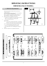
2.7 The stove is fitted with the Gazco Flue Sure System which
cuts off the gas supply to the burner if the flue does not
operate correctly. This means there may be insufficient flue
pull. If this happens, wait 10 before trying to relight.
Repeated shutdown may indicate a serious problem. You
must investigate both the flue and the Flue Sure device -
refer to Servicing Instructions, Replacing Parts, Section 3.
2. SAFETY PRECAUTIONS
1. CONTROL UPGRADE
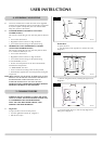
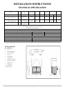
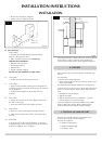
Flue Pipe Installation
The stove is factory built for rear and top flue exit
3.1 • Unpack the accessories carton and stove unit
• Position the stove observing all clearance measurements
• Adjust the balance of the stove using the bolts in the legs
to make it level
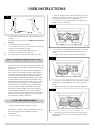
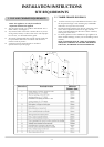
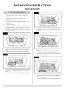
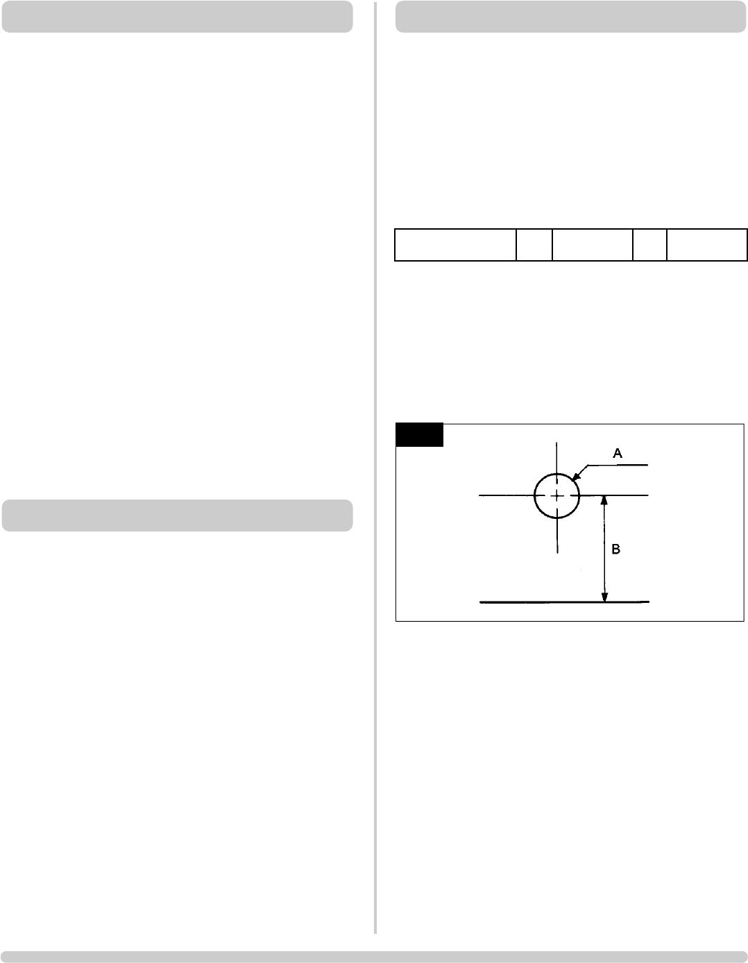
3.2 Rear Exit Flue
• Unpack the adjustable flue and terminal guard
• Take care not to lose fixings
• Decide on final stove position
• Ensure you comply with clearance for external flue
terminal, see Site Requirements, 1.
• Mark the centreline of the stove on the wall
• Mark the height from the hearth to the flue centre,
Diagram 1
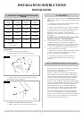
TAKE CARE WHEN MARKING OUT FOR THIS FLUE; IT IS
DIFFICULT TO MOVE FOLLOWING INSTALLATION
• Create a 152mm (6”) diameter hole for the flue by
a) Core Drill
b) Hammer and chisel
(We advise drilling small holes around the circumference for
method b). Make good at both sides of the hole.
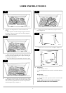
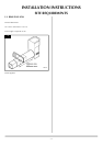
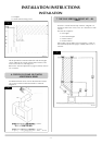
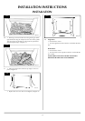
3.3 Setting the flue length
• Measure the total wall thickness and add 65mm - this
gives a minimum clearance between the back of the stove
and the wall.
• Insert the square cardboard fitment into the flue to
support the inner flue
• Cut through the flue and fitment, Diagram 2
1
AR0605
3. INSTALLATION OF THE STOVE
WALL THICKNESS
MIN
200 mm MAX 600 mm