16
INSTALLATION INSTRUCTIONS
INSTALLATION
• Open the door as set out in Section 5 of the Users
Instructions
• Remove all the protective packaging from the
components
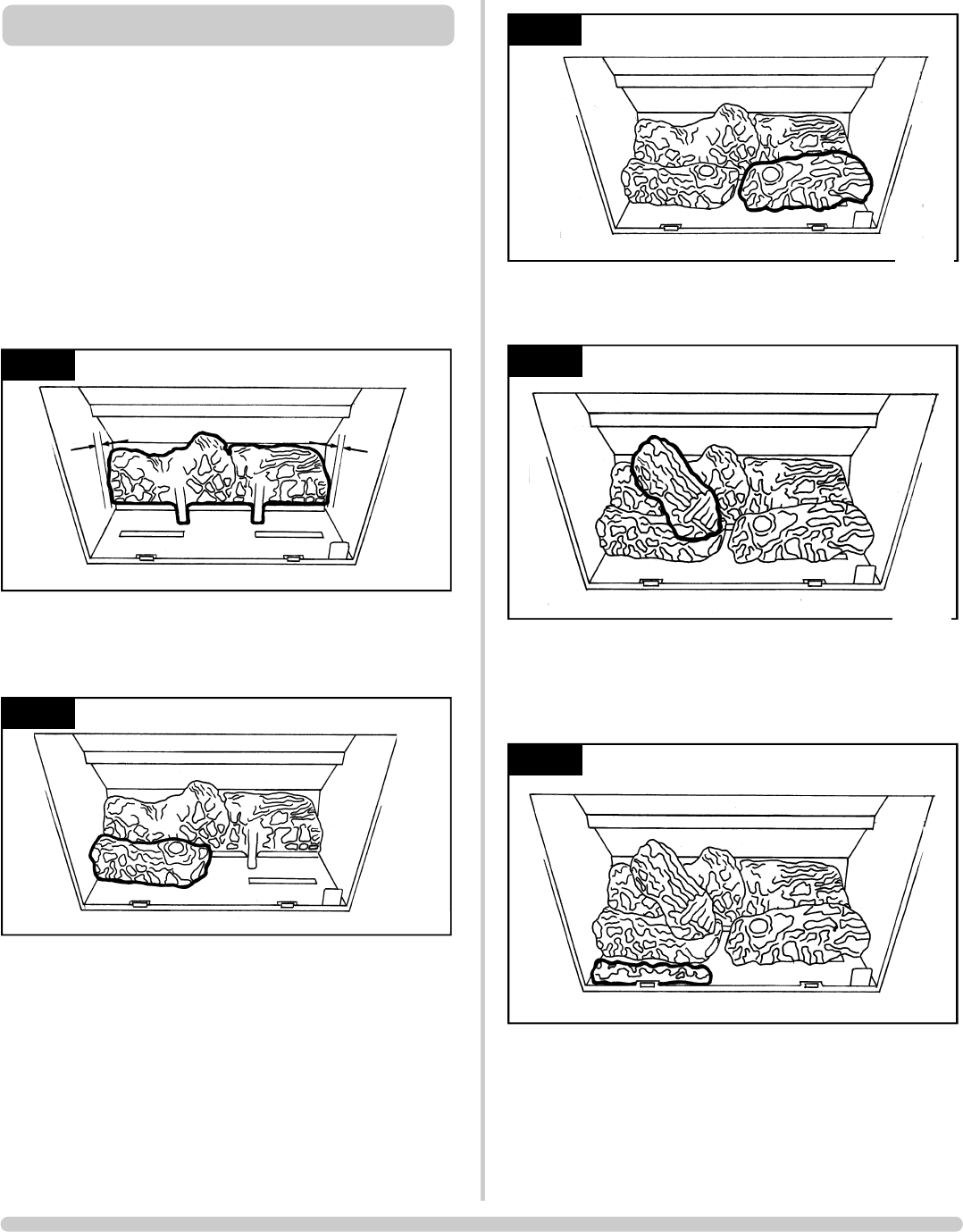
The fuel bed consists of 5 logs and 2 ash panels. The logs
have letters A,B,C,D and E moulded into them for
identification.
5.1 • Take the rear log A
• Place it up against the rear of the fire sitting on the two
flat ledges of the burner. The two legs of the log should sit
between the rear burner ports. See Diagram 7
• Ensure there is an equal gap between the sides of the firebox
at each end of the log
5.2 • Place log B on the left-hand side of the burner with the
location bar on its underside slid into the long slot of the
burner
• Make sure the log is as far left as possible, Diagram 8
5.3 • Place log C on the right-hand side of the burner with the
location bar on its underside slid into the long slot of the
burner.
• Make sure the log is as far right as possible, Diagram 9
AR1611
8
AR1610
7
5. FUEL BED ARRANGEMENT
5.4 • Place log D across from the rear log A to log B on the
left-hand side. There are cut-outs in both logs for location,
Diagram 10
5.5 There are two ash panels to lie across the front of the
burner.
• Place the panel with the flat edge facing the left side of
the firebox. There are location holes on this log fitting the
screw holes on the burner.
• Place the second ash panel to the right of the first, the
pointed end of this panel fitting the V shape and fitting the
screw holes on the burner.
• Ensure that both logs are horizontal to the burner ports.
14
AR1614
11
14
AR1613
10
AR1612
9


