


23
SERVICING INSTRUCTIONS
REPLACING PARTS
4.2 • Replace with a new ignition lead following the same
route as the old one
• Replace the valve cover and the pilot assembly
4.3 • Check operation of the new ignition lead
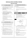
5.1 The piezo assembly used on this appliance is not serviceable
and is unlikely to fail.
5.2 If a new piezo is required, you must change the gas valve.
Refer to Section 6.
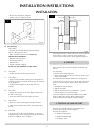
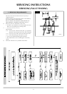
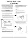
6.1 • Turn off the gas supply at the isolation device
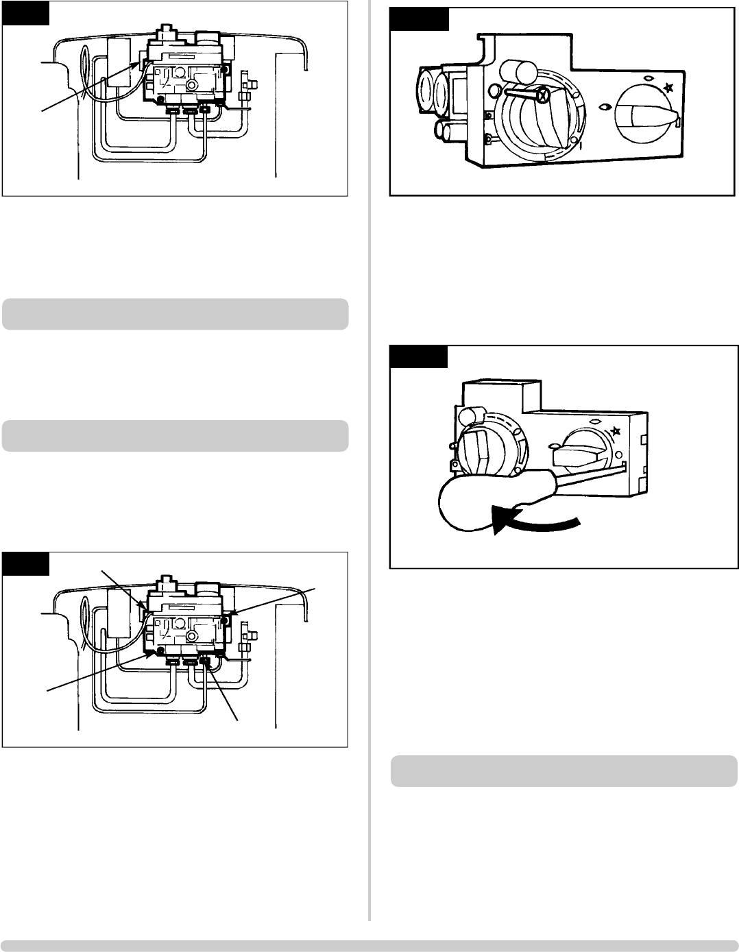
• Disconnect the 2 x 8mm and 1 x 4mm gas pipe fittings
at the back of the gas valve
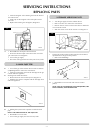
• Disconnect the thermocouple, Diagram 10
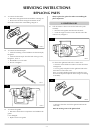
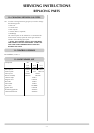
• Undo the single screw that secures the left-hand side of the
control cover, Diagram 11
AR0943
10
B
C
A
C
6. GAS VALVE
5. PIEZO
AR0943
9
B
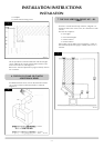
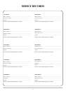
To release the right side of the control cover:
• Insert the narrow blade screwdriver into the slot shown
in Diagram 12
• Lever it gently and pull from the right side at the same
time to remove the cover
There is a small cylindrical metal spacer inside the cover.
This must be kept and replaced on the fixing screw during
re-assembly.
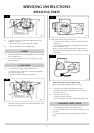
Note the existing route of the ignition lead
• Disconect the ignition lead from the valve body
6.3 • Disconnect the ignition lead from the gas valve
• Undo the two bolts securing the gas valve to the stove
and remove the valve
6.4 • Replace in reverse order
• Check all joints for gas leaks
• Check operation of the thermocouple and ignition lead
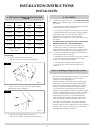
7.1 • Turn off the gas supply at the isolation device
• Undo the thermocouple connection from the back of the
gas valve
• Pull the sensor leads clear and remove the interrupter
block
7. MAGNETIC SAFETY VALVE
12
AR0916
11
AR0915