


21
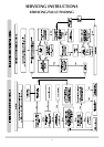
SERVICING INSTRUCTIONS
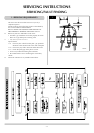
REPLACING PARTS
1.1 All main components can be replaced without removing the
stove from its installation. I
T IS ESSENTIAL THAT THE GAS SUPPLY
TO THE STOVE IS TURNED OFF AT THE ISOLATION DEVICE BEFORE
PROCEEDING FURTHER
.
1.2 If you need to remove the flue from the stove, you must
replace its seals.
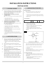
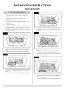
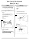
2.1 Turn the gas supply off at the isolation device. Ensure the
unit is cool.
• Remove the door and place to one side
• Remove the ceramic fuel bed components carefully
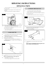
• Remove the three securing screws, two at the rear and
one at the front left hand side, Diagram 1
The burner venturi is engaged over the injector. When
removing the burner make sure you clear the injector to free
up the right side of the burner.
Take care too not to damage the pilot when removing the
burner.
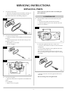
• Raise the left-hand side of the burner to clear the bracket
and draw forward
2.2 To replace the burner
• Engage the venturi over the injector making sure the
burner sits on top of the bracket
• Push the burner to the right and hold to insert the three
screws
NOTE: BEFORE REPLACING THE BURNER, ENSURE THE
SILICONE SEAL AROUND THE INJECTOR IS INTACT AND
CHECK THE VENTURI COVER IS ATTACHED.
AR1605
1
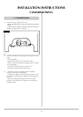
2. MAIN BURNER
1. GENERAL
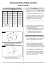
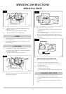
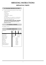
The pilot assembly has five components you can change:
1) Pilot burner bracket
2) Pilot injector
3) Electrode
4) Thermocouple
5) Gasket
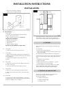
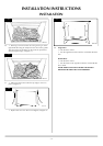
3.1 • Turn the gas supply off at the isolation device
• Remove the door and place to one side
• Remove the ceramic fuel bed components carefully
• Refer to Section 2 to remove the main burner
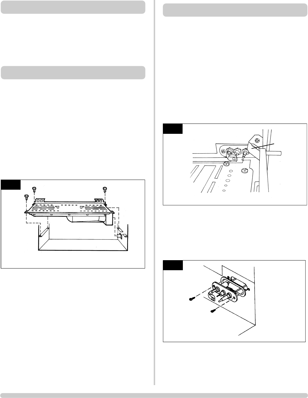
• Remove the thermocouple baffle taking note of how it is
positioned in Diagram 2
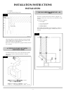
• Remove the two fixing screws from the pilot bracket,
Diagram 3.
• Gently draw the assembly out of the firebox to access the
nuts and ignition lead
NOTE: TAKE CARE NOT TO DAMAGE THE GASKET
AR0614
3
AR1609
2
thermo baffle
3. PILOT UNIT