


Embedded Intel® Atom Processor D2700 with Intel® NM10 Express Chipset
57
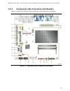
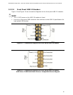
3.2.2.2 Add-in Card Connectors
The board has the following add-in card connectors:
PCI Express Full-/Half-Mini Card slot
Conventional PCI bus connector (with riser card support for up to two PCI cards)
Note the following considerations for the Conventional PCI bus connector:
The Conventional PCI bus connector is bus master capable.
SMBus signals are routed to the Conventional PCI bus connector. This enables
Conventional PCI bus add-in boards with SMBus support to access sensor data on
the board. The specific SMBus signals are as follows:
The SMBus clock line is connected to pin A40.
The SMBus data line is connected to pin A41.
The Conventional PCI bus connector also supports single-slot and dual-slot riser cards
for use of up to two bus master PCI expansion cards. In order to support two PCI bus
master expansion cards, the riser card must support the following PCI signal routing:
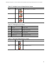
Pin A11: additional 33 MHz PCI clock
Pin B10: additional PCI Request signal (i.e., PREQ#2)
Pin B14: additional PCI Grant signal (i.e., GNT#2)
NOTE
BIOS IRQ programming for the second PCI slot on PCI riser card:
ID_SEL: AD20 (Device 4)
Second PCI slot INT Mapping:
INT A# (A6)
INT D# of mother board PCI slot.
INT B# (B7)
INT A# of mother board PCI slot.
INT C# (A7)
INT B# of mother board PCI slot.
INT D# (B8)
INT C# of mother board PCI slot.
NOTE
The Conventional PCI slot on this board does not support the PCI PHOLD
1
function. Due
to this limitation (errata), certain PCI cards may experience performance or detection
issues when DMA transfer is used as part of the PCI card operation.
1
PHOLD is the signal required to hold the bus during DMA transfers.