


Embedded Intel® Atom Processor D2700 with Intel® NM10 Express Chipset
59
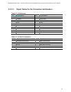
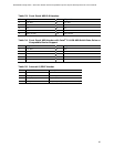
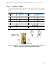
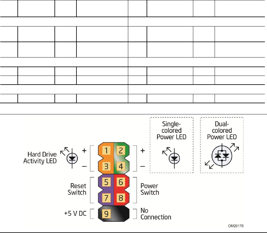
3.2.2.4 Front Panel Header
This section describes the functions of the front panel header. Table 28 lists the signal
names of the front panel header. Figure 12 is a connection diagram for the front panel
header.
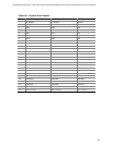
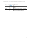
Table 28. Front Panel Header
Pin
Signal
In/
Out
Description
Pin
Signal
In/
Out
Description
Hard Drive Activity LED
Power LED
1
HD_PWR
Out
Hard disk LED
pull-up to +5 V
2
HDR_BLNK_GRN
Out
Front panel green
LED
3
HDA#
Out
Hard disk active
LED
4
HDR_BLNK_YEL
Out
Front panel yellow
LED
Reset Switch
On/Off Switch
5
Ground
Ground
6
FPBUT_IN
In
Power switch
7
FP_RESET#
In
Reset switch
8
Ground
Ground
Power
Not Connected
9
+5 V
Power
10
N/C
Not connected
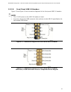
Figure 12. Connection Diagram for Front Panel Header