


Embedded Intel® Atom Processor D2700 with Intel® NM10 Express Chipset
60
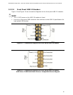
3.2.2.4.1 Hard Drive Activity LED Header
Pins 1 and 3 can be connected to an LED to provide a visual indicator that data is
being read from or written to a hard drive.
3.2.2.4.2 Reset Switch Header
Pins 5 and 7 can be connected to a momentary single pole, single throw (SPST) type
switch that is normally open. When the switch is closed, the board resets and runs the
POST.
3.2.2.4.3 Power/Sleep LED Header
Pins 2 and 4 can be connected to a single- or dual-color LED. Table 29 shows the
default states for a single-color LED.
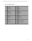
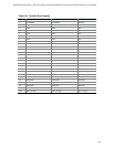
Table 29. States for a One-Color Power LED
LED State
Description
Off
Power off/hibernate (S5/S4)
Blinking
Sleeping (S3)
Steady Green
Running/Away (S0)
NOTE
The LED states listed in Table 29 are default settings that can be modified through
BIOS setup. Systems built with a dual-color front panel power LED can also use
alternate color state options.
3.2.2.4.4 Power Switch Header
Pins 6 and 8 can be connected to a front panel momentary-contact power switch. The
switch must pull the SW_ON# pin to ground for at least 50 ms to signal the power
supply circuitry to switch on or off. (The time requirement is due to internal debounce
circuitry on the board.) At least two seconds must pass before the power supply
circuitry will recognize another on/off signal.