


40
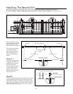
Step D-7:
Cut slot into driveway and lay the 25 foot power cable for the second operator in this slot (see Illustration on page 38).
NOTE: DO NOT attempt to splice the power cable, and DO NOT remove the connector from the end of the cable.
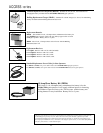
If you need a longer cable, 35 foot and 40 foot power cables are available (see Accessory Catalog).
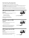
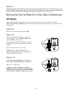
Setting the Control Board for Dual Gate Installations
DIP Switches
The Control Board DIP switches must be set to accommodate your particular type of installation. Since the
SNGL / DUAL, SEQ1, and SEQ2 DIP switches are used by dual gate operator systems, they will be discussed in the
following steps.
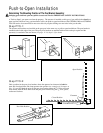
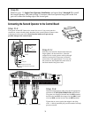
Step D-8:
Make sure the control box power switch is OFF.
Step D-9:
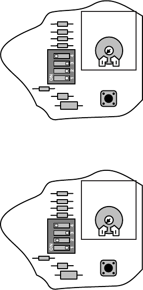
Unscrew and remove the control box cover. Use a
small screwdriver to move the SNGL / DUAL DIP
switch to DUAL (see illustration).
The order of gate operation ("sequencing") must now
be determined for your dual gate operators to function
properly.
Refer to the illustrations on the next page.
NOTE: The terms "FIRST OPERATOR" and
"SECOND OPERATOR" refer to a unit wired to the
terminal block of the same name.
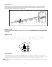
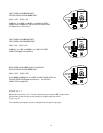
Step D-10:
BOTH OPERATORS OPEN SIMULTANEOUSLY
BOTH OPERATORS CLOSE SIMULTANEOUSLY
SEQ1 = ON SEQ2 = OFF
If SEQ1 is set to ON, and SEQ2 is set to OFF, the
FIRST OPERATOR and SECOND OPERATOR open
simultaneously (see illustration), and the FIRST OPERA-
TOR and SECOND OPERATOR close simultaneously.
OBSTRUCT
SENS.
PULL/PUSH
SEQ1
SNGL/DUAL
SEQ2
MIN MAX
LEARN
OBSTRUCT
SENS.
PULL/PUSH
SEQ1
SNGL/DUAL
SEQ2
MIN MAX
LEARN