


28
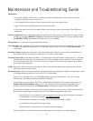
Connecting Additional Safety Devices
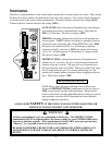
The GTO/PRO 2000 series operators are equipped with built-in obstruction sensitivity. These operators are designed to stop
and reverse the gate for 2 seconds when it comes in contact with an obstruction. However, obstruction sensitivity, even when
properly adjusted, may not be sensitive enough to prevent bodily injury in some circumstances. To augment protection
against entrapment, GTO suggests using safety edge sensors or photoelectric sensors. When installed, safety edges (or
photoelectric sensors) must be mounted in compliance with Underwriters Laboratories’ safety standard for gate operators,
UL 325. Review page 4 for information about mounting requirements for safety edges ("contact sensors") and photoelectric
sensors ("non-contact sensors").
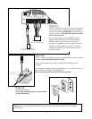
Refer to the sensor manufacturer’s instructions for information about installing these devices on a vehicular gate.
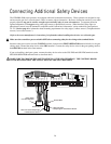
Make sure the control box power switch is OFF before connecting safety device wiring to the terminal blocks.
Insert the safety device wires into the CLS EDG terminal (located on the FIRST OPERATOR terminal block) for the gate
closing mode. Ground the safety device at the GRN terminal. Connect the safety device wires for the gate opening mode to
the OPN EDG terminal in the same manner.
If you are installing a dual gate system, connect the safety devices wires to the CLS EDG and OPN EDG terminals on the
SECOND OPERATOR terminal block as described above.
MAKE SURE TO GROUND THE SAFETY DEVICES AT THE GRN TERMINAL! THE CONTROL BOARD
COULD BE DAMAGED IF THE SAFETY DEVICES ARE NOT GROUNDED!
ON
SECOND OPERATORFIRST OPERATORPOWER IN ALARM ACCESSORY RCVR
SEQ1
SEQ2
LEARN
18VAC SOLAR
~~– +
RED
BLK
ORG
BLU
GRN
CLS EDG
OPN EDG
RED
BLK
BLU
ORG
ORG
BLU
WHT
GRN
GRN
CLS EDG
OPN EDG
R B G
Power Cable
from First Operator
Wire from Close Safety Edge
or Photoelectric Sensor
Wire from Open
Safety Edge or Photoelectric Sensor
Ground Wire
Ground Wire