


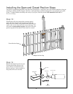
17
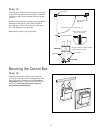
Step 15:
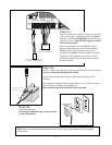
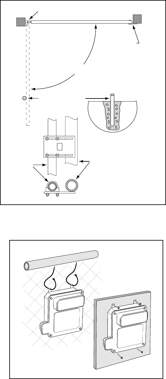
Close the gate. Position the closed position stop plate
on the end of the gate frame at mid-height. Extend the
stop plate to make contact with the fence post at that
position.
Install the closed position stop plate using appropriate
hardware for the type of gate (U-bolts for tube or
chain link gate, wood or lag screws for wood gates,
etc.). This hardware is not provided.
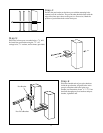
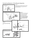
Reattach the operator to the gate bracket.
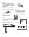
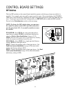
Mounting the Control Box
Step 16:
Mount the control box using the nylon cable ties
(provided) or another secure mounting method. The
control box must be mounted at least 3 feet above
the ground to protect it from rain splash, snow, etc.,
and at least 3 feet from an ac power source to
prevent electrical interference.
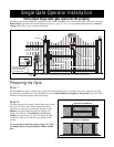
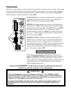
Closed Position
Stop Plate
Closed Position Stop Plate mounted
on metal post with u-bolts.
Open Position Stop
Wood, metal or concrete
post set in concrete.
Hinge point
The gate must open no more than 110°
Fence Post
Gate Post
TOP VIEW
SIDE VIEW