Maintenance & Service
Introduction
4
4-1
WARNIN
G
Section 4
Maintenance & Service
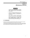
The Model 35360A TRACKER Display and 35300A
Detector contain no internal operator serviceable
parts. Disassembly of either unit could result in
electrical shock.
Always turn the 35360A TRACKER Display's power
off prior to connecting or disconnecting the
interface cable. Failure to do so may result in an
electrical shock.
When powering the 35360A TRACKER Display
from an AC line, always use a 3-wire grounding
type line cord such as the one supplied with the
90100 TRACKER System. In addition, only
connect the 35360A TRACKER Display to an AC
power outlet employing a third wire safety ground.
4.1 Introduction
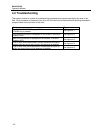
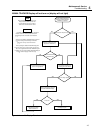
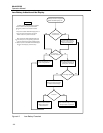
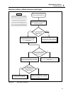
This section outlines steps that the operator may take to identify and correct problems. It also gives
instructions on how to order replacement parts or arrange for service if necessary.
For the purposes of troubleshooting, the system consists of three major components: detector, display,
and an interface cable. Even though these major components contain no internal operator serviceable
parts, a number of problems can be dealt with by the operator in the field environment.


