


Model 90100
Operators Manual
2-14
N
O
TE
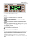
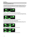
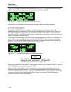
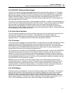
Figure 2-24 illustrates the locations of the annunciators on the VFD. The High Bias annunciator would
appear in place of the Low Bias annunciator should this condition be detected.
Figure 2-24. Positions of the Battery and Bias Annunciators
See Section 4 for information on how to deal with the LoBat, HiBias, and LoBias conditions.
2.4.10 Gain Setting Mode
The 35360A TRACKER Display uses several variables to determine an exposure's value: the
electrometer reading in Coulombs and Coulombs/min, the Display Units Conversion Factor (DUCF), an
Ion Chamber Calibration Factor (ICCF), the Air Density Correction Factor (ADCF), and a Front Panel
Gain Factor (FPGF). The FPGF's provide a means of adjusting the measurement readings from the front
panel of the 35360A TRACKER Display.
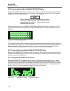
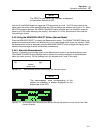
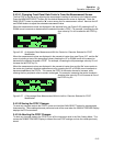
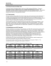
The 35360A TRACKER Display must be in the Gain Setting Mode before an FPGF can be changed. To
enter or exit the Gain Setting Mode, press and hold the GAIN SELECT button for approximately three
seconds. Entry into the Gain Setting Mode is indicated by a movement of the "X" cursor from the FPG
annunciator to one of the five FPGF values as shown in Figure 2-25.
Figure 2-25. The Gain Select Screen in the Gain Setting Mode
The FPGF's are automatically enabled upon
entering the Gain Setting Mode. They cannot be
disabled while the instrument is in this mode.
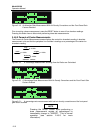
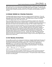
Subsequent presses of the GAIN SELECT button advance the "X" cursor through the FPGF's. Press the
UP or DOWN button to increase or decrease an FPGF.
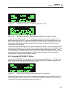
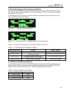
While in the Gain Setting Mode, all of the screens may be viewed and the measurement system will
function as it does in the Normal Mode. The FPGF's may be set either from the Gain Select screen, or
from one of the Measurement screens. Pressing the MEASURE SELECT button cycles the VFD through
a sequence consisting of the Absolute Measurement Screen, the Percent-of-Center Measurement
Screen, and back to the Gain Select Screen.