Operation
Real Panel Familiarization
2
2-3
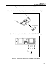
Display. Be sure to use the correct end of the
cable.
3. Secure the cable at each end by twisting the thumbscrews in a clockwise direction until tight.
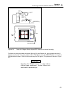
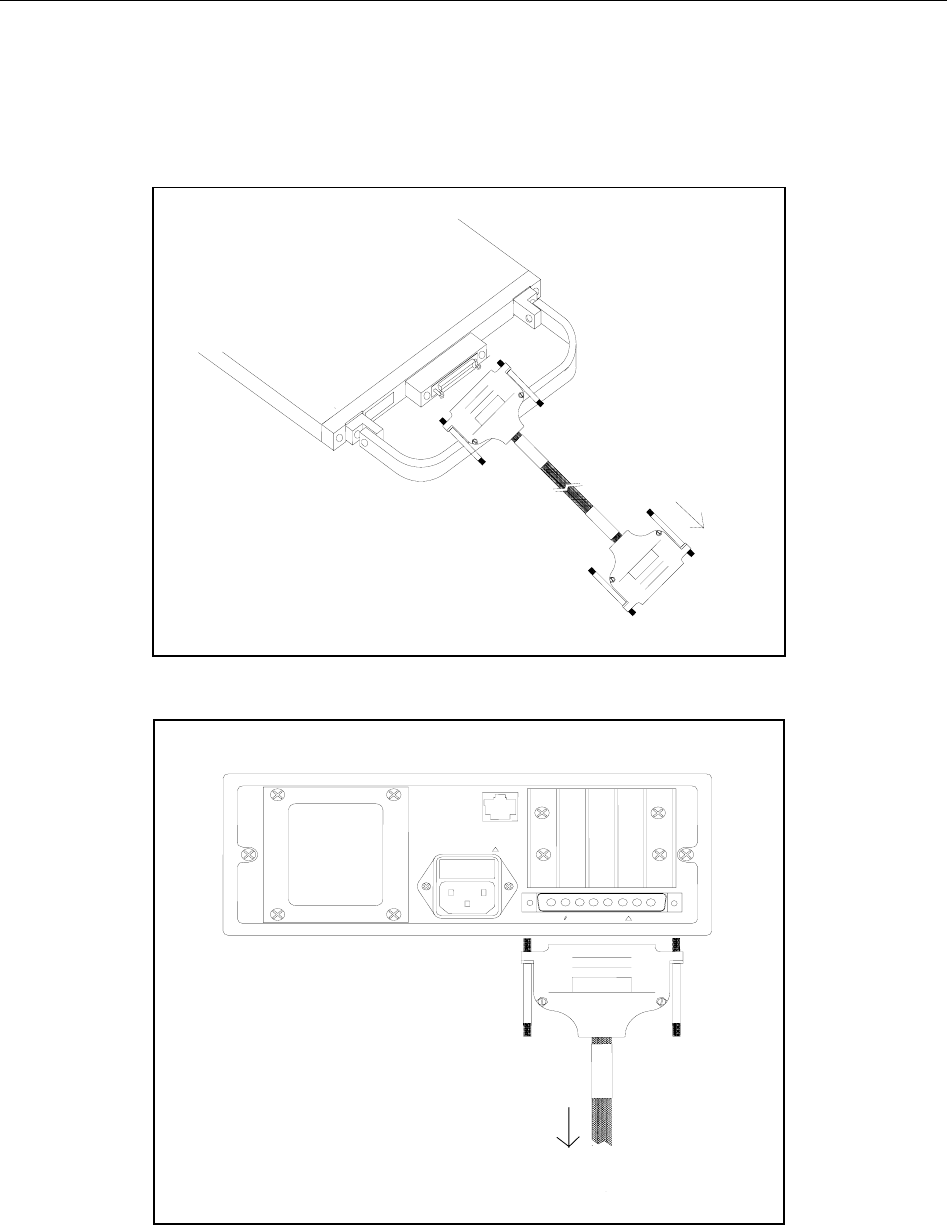
Figure 2-2. Connecting the Interface Cable to the Model 35360A TRACKER Display
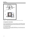
Figure 2-3. Connecting the Interface Cable to the Model 35300A Detector
DETECTOR INPUT
!
100-240V 50/60 Hz 50VA
!
COMPUTER
INTERFACE
RS-232
Rear panel of the Model 35360A TRACKER Display
To
Model 35300A
Detector
Model 35300A Detector
To Model 35360A TRAKCER Display


