


Model 90100
Operators Manual
3-4
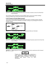
3.2.6 Serial Communications Port
A computer interface has been provided in the form of a DCE configured RS-232 port. This port is
configured for operation at 9600 baud and uses a standard Xon/Xoff handshaking protocol. The
associated RJ-45 type connector is located on the 35360A TRACKER Display's rear panel. This interface
provides the means for production testing and calibration, field customization by the user, and fully
programmable operation using appropriate software.
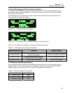
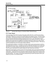
3.2.7 Electrometer
This block contains a fully guarded, five channel, single range, dual measurement mode electrometer. It
is capable of providing both dose and dose rate measurements from the five detector channels. The
connection to the electrometer's inputs is made through five coaxial inserts in a D-style receptacle located
on the 35360A TRACKER Display's rear panel. Also located within this connector are three single
conductor outputs for safety ground, signal ground, and ion chamber bias.
The measurement mode is user-selected from the front panel prior to the start of the exposure. In the
dose mode, the electrometer is operated in integrating mode with capacitive feedback. Prior to each
exposure the user must manually reset the electrometer to zero by pressing the front panel "RESET"
button. During dose rate measurements, the electrometer is operated in a non-integrating mode with
resistive feedback.
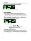
3.2.8 Multiplexer and A/D Converter
This block consists of an six channel analog multiplexer and 16 bit A/D Converter which operates under
the direct control of the microcontroller. Its main function is to convert the five analog voltage signals
produced by the Electrometer Block into digital signals for use by the microcontroller. It is also used to
measure the output of the 300 Volt Electronic Bias Supply. Although the 16 bit A/D Converter operates in
a unipolar mode, its zero measurement point is offset slightly below the zero output level of the
electrometer. This configuration provides optimal matching between the A/D's input span and
electrometer's 3 Volt full scale output swing. It also provides the ability to read the small negative
voltages which might result from electrometer leakage and offset drift.
A second 8-bit A/D Converter (actually located within the microcontroller) is used for measuring non-
critical internal parameters such as the battery voltage and current.
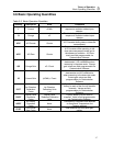
Full scale electrometer and A/D Converter values in electrical units are given in Table 3-1. The
corresponding values in radiological units are given in Table 3-2.
Table 3-1. Nominal Full Scale and Sensitivity in Electrical Units
Dose
Full Scale
Dose
Sensitivity
Rate
Full Scale
Rate
Sensitivity
1000.0 nC 0.1 nC 1000.0 nC/min 0.1 nC/min
Table 3-2. Nominal Dose and Rate Display Ranges in Radiological Units
Dose
Full Scale
Dose
Sensitivity
Rate
Full Scale
Rate
Sensitivity
3,520 R 0.1 R 3,520 R/min 0.1 R/min
3,093 rad 0.1 rad 3,093 rad/min 0.1 rad/min
30.93 Gy 1 mGy 30.93 Gy/min 1 mGy/min
30.93 Sv 1 mSv 30.93 Sv/min 1 mSv/min