


xx
,
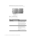
Figure 1-1. Front Panel Features . . . . . . . . . . . . . . . . . . . . . . . . . . . . . . . . . . . . . 1-2
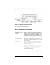
Figure 1-2. Features Behind the Front Bezel. . . . . . . . . . . . . . . . . . . . . . . . . . . . 1-3
Figure 1-3. Standard Back Panel Features. . . . . . . . . . . . . . . . . . . . . . . . . . . . . . 1-4
Figure 1-4. Ethernet Network Interface Cards. . . . . . . . . . . . . . . . . . . . . . . . . . . 1-6
Figure 1-5. Expansion Slot Locations. . . . . . . . . . . . . . . . . . . . . . . . . . . . . . . . . . 1-7
Figure 1-6. A Typical PowerVault Filer System . . . . . . . . . . . . . . . . . . . . . . . . . 1-10
Figure 2-1. Rack Vertical Rail (With 1-U Marks). . . . . . . . . . . . . . . . . . . . . . . . . . 2-5
Figure 2-2. Front of Rack Adapter Rail — Whole-U and Half-U Alignment . . . . . 2-6
Figure 2-3. Back of Rack Adapter Rail — Whole-U and Half-U Alignment. . . . . . 2-7
Figure 2-4. Installing Rack Adapter Rails . . . . . . . . . . . . . . . . . . . . . . . . . . . . . . . 2-7
Figure 2-5. Installing a Cage Nut . . . . . . . . . . . . . . . . . . . . . . . . . . . . . . . . . . . . . 2-9
Figure 2-6. Filer Installed in a Rack . . . . . . . . . . . . . . . . . . . . . . . . . . . . . . . . . . . 2-9
Figure 2-7. Cable Management Clip Installed . . . . . . . . . . . . . . . . . . . . . . . . . . 2-10
Figure 2-8. Filer Connections To the First PowerVault 700N
Storage System. . . . . . . . . . . . . . . . . . . . . . . . . . . . . . . . . . . . . . . . 2-12
Figure 2-9. Two FC-AL Connections to Multiple PowerVault 700N
Storage Systems . . . . . . . . . . . . . . . . . . . . . . . . . . . . . . . . . . . . . . . 2-13
Figure 2-10. SCSI Connections to Tape Backup Device . . . . . . . . . . . . . . . . . . . 2-15
Figure 2-11. Built-In Ethernet Connector Location . . . . . . . . . . . . . . . . . . . . . . . 2-17
Figure 2-12. Ethernet Network Interface Controllers . . . . . . . . . . . . . . . . . . . . . 2-17
Figure 2-13. Filer Console Port Location . . . . . . . . . . . . . . . . . . . . . . . . . . . . . . . 2-19
Figure 2-14. Filer Power Supplies . . . . . . . . . . . . . . . . . . . . . . . . . . . . . . . . . . . . 2-21
Figure 3-1. Front Panel LEDs. . . . . . . . . . . . . . . . . . . . . . . . . . . . . . . . . . . . . . . . 3-2
Figure 3-2. Filer Back Panel — Power Supply LEDs . . . . . . . . . . . . . . . . . . . . . . 3-3
Figure 3-3. Built-In Ethernet LEDs. . . . . . . . . . . . . . . . . . . . . . . . . . . . . . . . . . . . 3-5
Figure 3-4. LEDs on the Single-Port Ethernet Card . . . . . . . . . . . . . . . . . . . . . . . 3-6
Figure 3-5. LEDs on the Quad-Port Ethernet Card . . . . . . . . . . . . . . . . . . . . . . . 3-7
Figure 3-6. LEDs on the Gigabit Ethernet Card . . . . . . . . . . . . . . . . . . . . . . . . . . 3-8
Figure 3-7. Boot Messages . . . . . . . . . . . . . . . . . . . . . . . . . . . . . . . . . . . . . . . . 3-12
Figure 4-1. Diagnostics Checklist . . . . . . . . . . . . . . . . . . . . . . . . . . . . . . . . . . . . 4-6
Table 1-1. Front Panel Features Defined . . . . . . . . . . . . . . . . . . . . . . . . . . . . . . 1-2
Table 1-2. Features Behind the Front Bezel Described . . . . . . . . . . . . . . . . . . . 1-3
Table 1-3. Back Panel Features Described. . . . . . . . . . . . . . . . . . . . . . . . . . . . . 1-4
Table 1-4. Fibre Channel Arbitrated Loop Disk Adapters . . . . . . . . . . . . . . . . . . 1-6
Table 1-5. Available Slots — All Filers . . . . . . . . . . . . . . . . . . . . . . . . . . . . . . . . 1-7
Table 2-1. Temperature and Humidity Requirements . . . . . . . . . . . . . . . . . . . . 2-2
Table 2-2. Electrical Power Requirements . . . . . . . . . . . . . . . . . . . . . . . . . . . . . 2-2
Table 2-3. Equipment Dimensions and Weight (With Filler Panel). . . . . . . . . . . 2-3
Table 2-4. Clearance Requirements (With Filler Panel) . . . . . . . . . . . . . . . . . . . 2-3
Table 2-5. Network Connectivity . . . . . . . . . . . . . . . . . . . . . . . . . . . . . . . . . . . 2-16
Table 2-6. Ethernet Cabling Requirements . . . . . . . . . . . . . . . . . . . . . . . . . . . 2-16
Table 2-7. Serial Console Connector Assignments . . . . . . . . . . . . . . . . . . . . . 2-18