


32
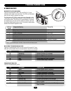
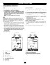
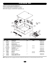
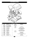
ELECTRICAL BOX
2
13
9
12
9
4
1
11
8
10
7
3
5
6
14
15
ITEM PART # DESCRIPTION QTY NOTES PROVIDED IN KIT
1 K001A5566 Control Board 1 Individual Part
2 03-8024-K Contactor, 3 Pole Reversing 1 Individual Part
3 10-19198 Control Box Cover 1 Individual Part
4 10-19199 Mounting Bracket 1 Individual Part
5 21-3260-1 Transformer, 50/60HO, 60VA 1 Individual Part
6 31-13703 Standoffs for Optional Loop Detector 8 Optional
7 35-310-032 Fuse, Glass Body 3.2AMP 3AG 1 Individual Part
8 G71-416-7NH Loop Detector 2 Optional
9 42-114-2 Terminal Strip, 14 Poles 1 Individual Part
10 42-19200 Radio Block 4 Pole 1 Individual Part
11 42-8116-1 Terminal Strip, PCB 16 Pole 1 Individual Part
12 74-19201 Control Box 1 Individual Part
13 23-3001 Switch 1n 1 1PH Units Complete Assembly
23-3005 Switch 3n 3PH Units
14 31-G055 Standoffs for GL Board 3 Individual Part
15 25-2015 Overload, 15AMP (230V 1PH) 1 Individual Part
25-2006 Overload, 6AMP (115V 1PH)
INDIVIDUAL PARTS AND KITS
COMPLETE ELECTRICAL BOX REPLACEMENT KITS
To order a complete electrical box replacement kit, add a K-
prefix to the model number of your operator. For example:
HS670-100-21 (Operator) = K-HS670-100-21 (Electrical Box Kit)
NOTE: Single phase units are equipped with either an external line break device or an internal pilot-duty thermal O/L device.