


2
CARTON INVENTORY
Before beginning your installation check that all components
were supplied and received undamaged. Refer to list below
for factory supplied parts.
Description Qty.
Bolt 1/4-20 (for Limit Shoe) 4
Lockwasher 1/4 4
Hex Nut 1/4-20 4
Screw #10-24 (for Gate Stop) 4
Lockwasher #10 4
Hex Nut #10-24 4
Limit Shoe 2
Gate Warning Sign 2
Vent Cap 1
Gate Stops 2
PBS, Stop 1
HARDWARE KIT
When you see the above Safety Symbols and Signal Words on
the following pages, they will alert you to the possibility of
SERIOUS INJURY or DEATH if you do not comply with the
warnings that accompany them. The hazard may come from
something mechanical or from electric shock. Read the warnings
carefully.
When you see this Signal Word on the following pages, it will
alert you to the possibility of damage to your gate and/or the gate
operator if you do not comply with the cautionary statements that
accompany it. Read them carefully.
IMPORTANT NOTE
• BEFORE attempting to install, operate or maintain the operator,
you MUST read and fully understand this manual and follow all
safety instructions.
• DO NOT attempt repair or service of your commercial door and
gate operator unless you are an Authorized Service Technician.
TABLE OF CONTENTS
OPERATOR SPECIFICATIONS
Carton Inventory . . . . . . . . . . . . . . . . . . . . . . . . . . . . . . . . . . . . .2
Operator Features . . . . . . . . . . . . . . . . . . . . . . . . . . . . . . . . . . . .3
Operator Dimensions and Horsepower Chart . . . . . . . . . . . . . . .4
UL325 Model Classifications . . . . . . . . . . . . . . . . . . . . . . . . . . . .5
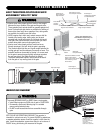
OPERATOR WARNINGS
Safety Installation Information . . . . . . . . . . . . . . . . . . . . . . . . . .6
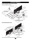
Suggested Entrapment Protection Device Locations . . . . . . . . . .7
Safety Precautions for Open Roller Gates . . . . . . . . . . . . . . . . . .8
Warning Sign Placement . . . . . . . . . . . . . . . . . . . . . . . . . . . . . . .8
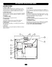
INSTALLATION
Concrete Pad . . . . . . . . . . . . . . . . . . . . . . . . . . . . . . . . . . . . . . . .9
Drive Rail . . . . . . . . . . . . . . . . . . . . . . . . . . . . . . . . . . . . . . . . . . .9
Operator Mounting . . . . . . . . . . . . . . . . . . . . . . . . . . . . . . . . . . .9
Vent Cap . . . . . . . . . . . . . . . . . . . . . . . . . . . . . . . . . . . . . . . . . .10
Limit Shoes . . . . . . . . . . . . . . . . . . . . . . . . . . . . . . . . . . . . . . . .10
Gate Stops . . . . . . . . . . . . . . . . . . . . . . . . . . . . . . . . . . . . . . . . .11
Suspension System . . . . . . . . . . . . . . . . . . . . . . . . . . . . . . . . . .11
Manual Operation . . . . . . . . . . . . . . . . . . . . . . . . . . . . . . . . . . .11
WIRING
Power Wiring Installation . . . . . . . . . . . . . . . . . . . . . . . . . . . . .12
On/Off Switch Power Wiring . . . . . . . . . . . . . . . . . . . . . . . . . . .13
ADJUSTMENT
Hall Effect Sensor Adjustment . . . . . . . . . . . . . . . . . . . . . . . . . .14
Force Adjustment . . . . . . . . . . . . . . . . . . . . . . . . . . . . . . . . . . . .14
PROGRAMMING
UL325 Entrapment Protection . . . . . . . . . . . . . . . . . . . . . . . . . .15
Control Board Illustration . . . . . . . . . . . . . . . . . . . . . . . . . . . . .16
Program Settings (DIP Switch) . . . . . . . . . . . . . . . . . . . . . .17-18
Programming the Radio Receiver . . . . . . . . . . . . . . . . . . . . . . .19
OPTIONAL CONTROL DEVICES
Sequenced Access Management System (SAMS) . . . . . . . . . . .20
Accessory Wiring . . . . . . . . . . . . . . . . . . . . . . . . . . . . . . . . . . .21
Control Connection Diagrams . . . . . . . . . . . . . . . . . . . . . . . . . .22
OPERATION AND MAINTENANCE
Important Safety Instructions . . . . . . . . . . . . . . . . . . . . . . . . . .23
TROUBLESHOOTING
GL Board Features . . . . . . . . . . . . . . . . . . . . . . . . . . . . . . . . . . .24
Electrical Troubleshooting . . . . . . . . . . . . . . . . . . . . . . . . . .25-26
Hydraulic System Troubleshooting . . . . . . . . . . . . . . . . . . . . . .27
Mechanical Troubleshooting . . . . . . . . . . . . . . . . . . . . . . . . . . .27
Hydraulic System Information . . . . . . . . . . . . . . . . . . . . . . .28-29
SINGLE PHASE WIRING DIAGRAM
. . . . . . . . . . . . .30
THREE PHASE WIRING DIAGRAM
. . . . . . . . . . . . . .31
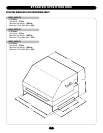
ELECTRICAL BOX
. . . . . . . . . . . . . . . . . . . . . . . . . . .32
ILLUSTRATED PARTS
. . . . . . . . . . . . . . . . . . . . . . . .33
WARRANTY POLICY
. . . . . . . . . . . . . . . . . . . . . . . . .34
OPERATOR NOTES
. . . . . . . . . . . . . . . . . . . . . . . . . .35
REPAIR PARTS AND SERVICE
. . . . . . . . . . . . . . . . .36
Mechanical
Electrical
WARNING
CAUTION
WARNING
WARNING
WARNING
CAUTION
WARNING
WARNING
WARNING
CAUTION
WARNING
WARNING