


3
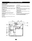
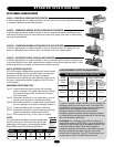
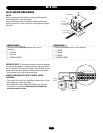
G. LIMIT SWITCH
All limit switches are oil tight and watertight, and of NEMA 3, 4,
and 13 construction. Open switch for right hand, close switch for
left hand.
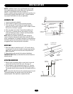
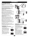
H. DRIVE WHEELS
Drive wheels are constructed of polyurethane material on a steel
hub and have a hardness factor of 95. HS670 1HP = 1 1/2" wide,
6" diameter; HS670 2HP= 2" wide, 6" diameter.
I. HYDRAULIC MOTOR
Roller vane, free wheeling type with a displacement of 12 cubic
inches per revolution.
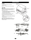
J. SUSPENSION SYSTEM
Incorporates two compression springs. HS670 1HP and HS670
2HP use different compression springs. See also page 11.
K. HALL EFFECT (RPM) SENSOR ASSEMBLY
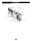
H
I J
K
G
G
F
D
E
B
C
A
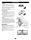
OPERATOR SPECIFICATIONS
OPERATOR FEATURES
A. MOTOR 1 AND 2 HP
The motors used in the HS670 GC and HS670 GI are T.E.F.C.
(totally enclosed, fan cooled) and operate at 3450 R.P.M. They
incorporate a built-in manually resettable thermal overload.
B. DIRECTIONAL VALVE
Directional valve is 3 position, 4 way. It incorporates 2 solenoids
which are 24 VDC. The power required for operation is rectified
from 24 VAC.
C. HYDRAULIC BRAKE
Dual valve system limits gate over travel.
D. BYPASS VALVE
Incorporates a handle at side of pump. When positioned
downward, it will allow manual operation of the gate.
E. RELIEF VALVE
Built into pump. Set at 600 p.s.i. for HS670 1HP and 1500 p.s.i.
for HS670 2HP.
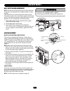
F. VENT CAP
When removed, you may add hydraulic oil. Must be on during
operator operation.