


14
ADJUSTMENT
To reduce the risk of SEVERE INJURY or DEATH:
• Disconnect power BEFORE performing ANY adjustments.
WARNING
CAUTION
WARNING
WARNING
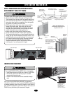
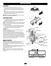
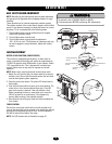
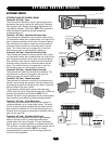
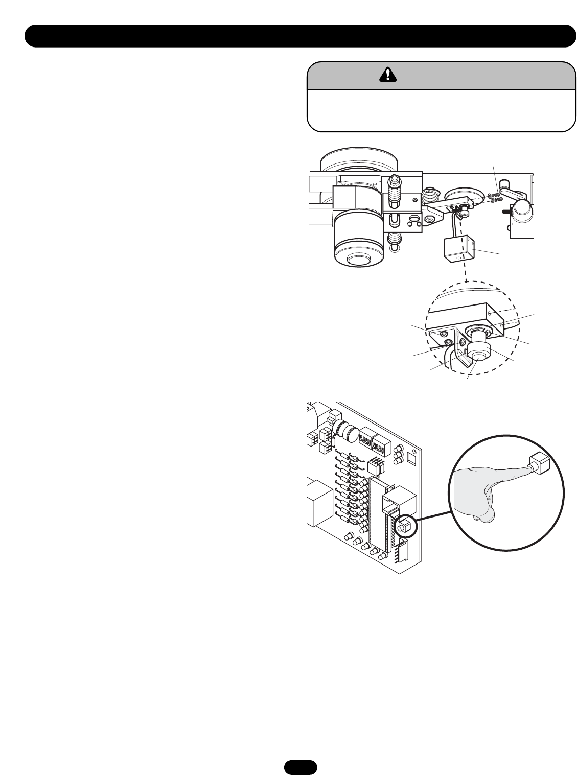
HALL EFFECT SENSOR ADJUSTMENT
NOTE: Normally the hall effect sensor does not need adjustment,
but may go out of alignment due to shipping vibration or rough
handling.
These operators use an internal entrapment protector system.
This system consists of the control board, magnet, and hall effect
sensor. It may become necessary to adjust the sensor for correct
alignment. To do so please perform the following steps:
1. The hall effect sensor must be centered over the magnet.
Adjust with horizontal screws.
2. The hall effect sensor must be level.
3. The hall effect sensor air gap should be adjusted to
.010 - .015 of an inch. (The thickness of a business card may
be used to gauge the correct distance). Adjust with vertical
screws.
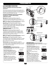
FORCE ADJUSTMENT
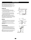
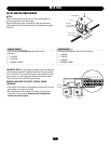
MOTOR LEARN FUNCTION (FORCE PROFILE)
This function is preprogrammed at factory. If either board or
motor is replaced, the controller will need to be programmed to
“LEARN” the specific motor RPM profile of your operator. Switch
“S3” is provided for this. This is important for accurate force
control. Failure to do so may result in improper and unsafe
operation.
NOTE: Motor Learn must be performed in stand alone mode.
1. Detach the unit from the gate, the motor needs to be learned
without a load. (Do not use the manual release, the limit shaft
must be turning during learn sequence.)
2. Press the motor learn button. The yellow LED should start to
flash rapidly.
3. Push and hold down either the open or the close buttons. The
motor will run for a few seconds and then stop. If the LED
goes out the motor is learned. If the unit activates a limit
before completing the learn or some other error occurs the
LED will go back to on continuously. If this happens try
learning while running in the opposite direction.
4. Reconnect the unit to the gate, reset the limits and adjust the
force control.
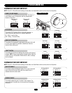
FORCE CONTROL
Set the force control pot such that the unit will complete a full
cycle of gate travel but can be reversed off an obstruction without
applying an unreasonable amount of force. On most operators
this will be around the middle of the range.
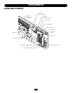
NOTE: For LED location refer to illustration on page 16.
Shaft
Hall Effect
Sensor
Vertical Adjustment
Screws
Horizontal Adjustment
Screws
Magnet
Shaft Retainer
Bushing
Cover
Cover Screws
Motor
Learn
Button (S3)