


10
INSTALLATION
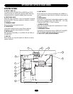
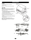
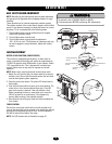
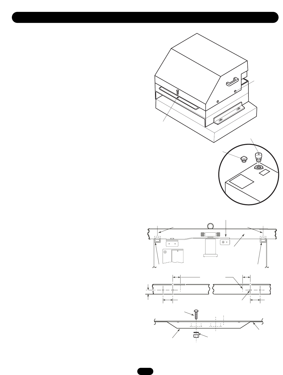
Remove Bolt to
Take Cover Off
Loosen Screw to
Remove Cover
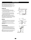
Vent Cap
IMPORTANT: Do Not
Use Cover Handles
to Move Unit
Tank
Threaded
Plug
VENT CAP
1. Remove the threaded plug from the pump tank.
2. Install the vent cap.
NOTE: Never run the operator without the vent cap installed.
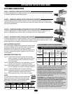
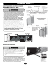
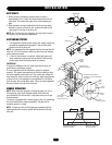
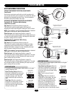
LIMIT SHOES
NOTE: The limit shoes are slotted, so minor adjustments may be
made later for the fine tuning of the fully open and close
positions. Also, note that the limit switches themselves may be
slightly adjusted up or down.
1. Cut wire ties to release limit switch levers and RPM assembly
to the up right position. These items are held down by wire ties
to facilitate for initial gate installation.
2. Manually open the gate to the full position.
3. Locate the open limit switch lever and mark its position.
4. Manually close the gate to the full close position.
5. Locate the close limit switch lever and mark its position on the
drive rail.
6. Manually open the gate about halfway. Measure and drill holes
to mount limit shoes
7. Secure both limit shoes to underside of drive rail.
NOTE: It is highly suggested that gate stops be installed to the
gate at the fully open and closed positions. See next page for
installation instructions.
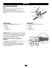
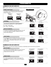
Mark Centerline Mark Centerline
Drive Rail
Limit Switch Limit Switch
Centerline Marks
9/32" Diameter
Holes
Bottom of
Drive Rail
1/4"-20 Screw
Washer & Nut
Limit Shoe
1-1/16"
2"
3"
RPM Assembly
TOP
VIEW
TOP
VIEW
SIDE
VIEW
2"
3"