Section 2, Engineering Guidelines ATLAS 550 System Manual
30 © 2002 ADTRAN, Inc. 61200305L1-1F
CONTROL IN Port
The CONTROL IN port (RJ-45) connects to a computer or modem or to another ATLAS 550 unit. The
CONTROL port input provides the following functions:
• Accepts EIA-232 input from a PC or a modem (for controlling the ATLAS 550)
• Operates at 2400, 9600, 19200, or 38400 bps
• Acts as input for either VT100 terminal or PC (with terminal emulation software) control
• Acts as an interface for flash memory software downloads and configuration transfers using XMODEM
The
CONTROL IN connection follows, and Table 4 shows the pinout.
CONTROL OUT Port
The CONTROL OUT port (RJ-48C) connects to other ADTRAN products’ CHAIN IN connectors. The
CONTROL port output provides the following:
• EIA-232 output to chain control to other ADTRAN equipment, such as a TSU 120 or another ATLAS
• 2400, 9600, 19200, or 38400 bps operation
• Automatic setup; no user input required
The
CONTROL OUT connection follows, and Table 5 shows the pinout.
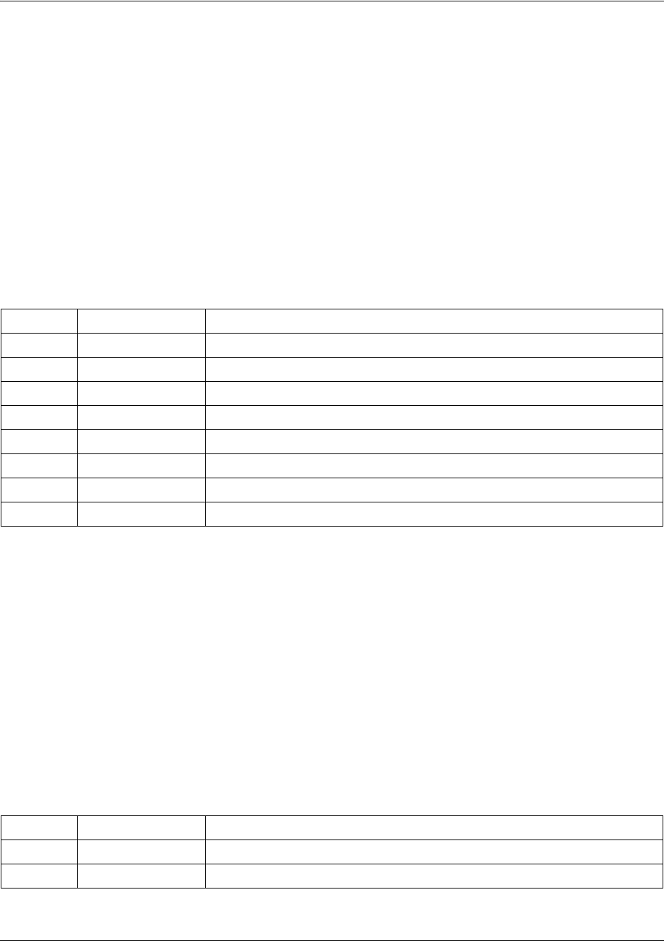
Connector type RJ-48C
Table 4. CONTROL IN Pinout
PIN NAME DESCRIPTION
1 GND Ground - connected to unit chassis
2 RTS Request to send - flow control
3 RXDATA Data received by the ATLAS 550
4 DTR Data terminal ready
5 TXDATA Data transmitted by the ATLAS 550
6 CD Carrier detect
7 UNUSED —
8 CTS Clear to send - flow control
Connector type RJ-48C
Table 5. CONTROL OUT Pinout
PIN NAME DESCRIPTION
1 GND Ground - connected to unit chassis. Connects to GND of next unit.
2 UNUSED —


