


6-4
S
uperWorkstation 7045A-C3/7045A-CT User's Manual
6-3 System Fans
Two 8-cm PWM chassis fans provide air intake while one 9-cm PWM exhaust fan
expels hot air from the chassis. All are low-noise fans that result in very low system
noise levels. The chassis is also fi tted with an air shroud to concentrate the fl ow of
cooling air through the system. The fans should be connected to headers on the
serverboard (see Chapter 5).
The power supply includes redundant cooling fans. If one fan fails, the rpm of the
remaining fan will ramp up its rpm to provide suffi cient cooling. The Power Fail LED
will illuminate and an audible alarm will sound, which can be silenced with a but-
ton on the power supply. If a power supply fan fails, you should replace the power
supply at your earliest convenience.
Fan Failure
Under normal operation, the chassis fans, the exhaust fan and the power supply
fans run continuously. The chassis fans are hot-swappable and can be replaced
without powering down the system.
Replacing Chassis Cooling Fans
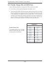
Removing a Fan
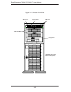
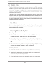
First locate the failed chassis fan by removing the top/left chassis cover (see
Chapter 2 for details). Locate the fan that has stopped working.
Depress the locking tab on the failed fan: on a chassis fan, push the tab on
the side of the housing inward, on the exhaust fan push down on the colored
tab.
With the tab depressed, pull the unit straight out (see Figure 6-3). The wiring
for these fans has been designed to detach automatically.
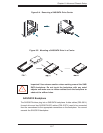
Installing a New Fan
Replace the failed fan with an identical one (available from Supermicro)
Install it in the same position and orientation as the one you removed; it
should click into place when fully inserted.
Check that the fan is working then replace the top/left side chassis panel.
1.
2.
3.
1.
2.
3.