


5-18
S
uperWorkstation 7045A-C3/7045A-CT User's Manual
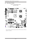
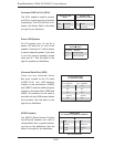
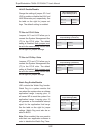
Universal Serial Bus (USB)
There are two Universal Serial
Bus ports located on the I/O panel
(USB0/1/2/3), four USB headers
located on the serverboard (USB4/5
and USB6/7) and two additional ports
located on the board itself (USB8 and
USB9). The headers can be used to
provide front side USB access (cables
not included). See the table on the
right for pin defi nitions.
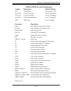
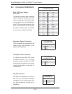
Universal Serial Bus
Pin Defi nitions (USB)
USB0/1/2/3/8/9
Pin # Defi nition
USB4/5, USB6/7
Pin # Defi nition
1 +5V 1 +5V
2 PO- 2 PO-
3 PO+ 3 PO+
4 Ground 4 Ground
5 N/A 5 Key
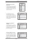
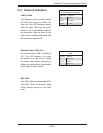
Power LED/Speaker
On JD1 header, pins 1-3 are for a
power LED and pins 4-7 are for the
speaker. Close pins 4-7 with a jumper
to use an external speaker. If you wish
to use the onboard speaker, please
close pins 6-7. See the table on the
right for speaker pin defi nitions.
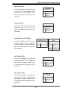
Power LED/Speaker
Connector (JD1)
Pin Setting Defi nition
Pins 6-7 Internal Speaker
Pins 4-7 External Speaker
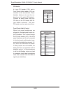
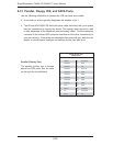
SGPIO Headers
The SGPIO (Serial General Purpose
Input/Output) headers are used to
communicate with a system-monitor-
ing chip on the backplane. See the
table on the right for pin defi nitions.
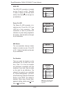
SGPIO Header
Pin Defi nitions (T-SGPIO-1/T-SGPIO-2)
Pin# Defi nition Pin Defi nition
1NC 2 NC
3 Ground 4 DATA Out
5 Load 6 Ground
7 Clock 8 NC
NC = No Connection
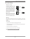
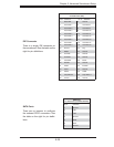
Overheat LED/Fan Fail (JOH1)
The JOH1 header is used to connect
an LED to provide warning of chassis
overheating. This LED will blink to in-
dicate a fan failure. Refer to the table
on right for pin defi nitions.
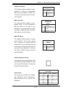
Overheat LED
Pin Defi nitions (JOH1)
Pin# Defi nition
1 5vDC
2 OH Active
OH/Fan Fail LED
States
State Message
Solid Overheat
Blinking Fan Fail